
Light coupling device and image projection apparatus using the same

a technology of light coupling and image projection, which is applied in the direction of picture reproducers, picture reproducers using projection devices, instruments, etc., can solve the problems of large image implementation or projection on a screen of large size, severe image flickering, and inability to provide clear image quality. to achieve the effect of reducing image size, reducing image size and reducing image quality

Inactive Publication Date: 2003-12-04
SAMSUNG ELECTRONICS CO LTD
View PDF4 Cites 7 Cited by
  • Summary
  • Abstract
  • Description
  • Claims
  • Application Information

AI Technical Summary

Problems solved by technology

However, while such methods magnify images, they do not provide clear image quality.
Therefore, when an image is simultaneously implemented or projected on multiple screens having different sizes, the image implemented or projected on a screen of large size becomes dark and has a severe degree of image flickering compared to images displayed on the other screens.
Further, there exists a problem in that an image size should be reduced in order to solve the darkness and flickering problems.

Method used


Image

  • Light coupling device and image projection apparatus using the same
  • Light coupling device and image projection apparatus using the same
  • Light coupling device and image projection apparatus using the same

Examples


Embodiment Construction

[0034] Hereinafter, exemplary embodiments of the present invention are described with reference to the accompanying drawings.

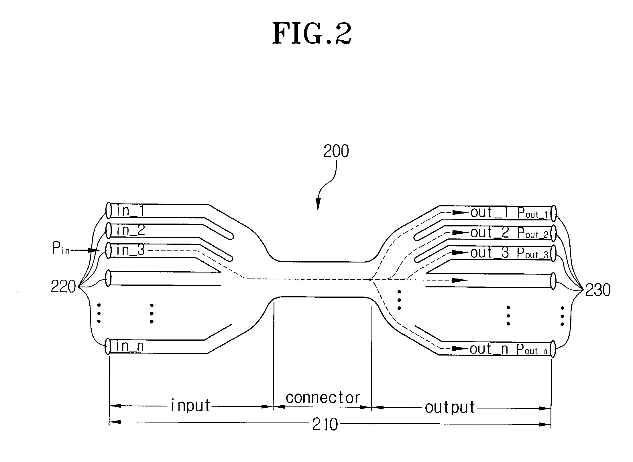
[0035] FIG. 2 shows a basic configuration of a light coupling device or a directional coupler (DC) having an (n.times.n) structure according to an exemplary embodiment of the present invention, with n being a positive integer.

[0036] Referring to FIG. 2, an (n.times.n) directional coupler 200 according to an exemplary embodiment of the present invention has a photoconductive medium 210, first lenses 220, and second lenses 230. The photoconductive medium 210 is composed of optical fibers and transmits light beams, such as laser beams. Light paths in FIG. 2 are indicated by dotted lines.

[0037] The photoconductive medium 210 has multiple input terminals in.sub.--1, in.sub.--2, in.sub.--3, . . . , in_n, that is, n input terminals; and multiple output terminals out.sub.--1, out.sub.--2, out.sub.--3, . . . , out_n, that is, n output terminals. The number of the input...


PUM


Abstract

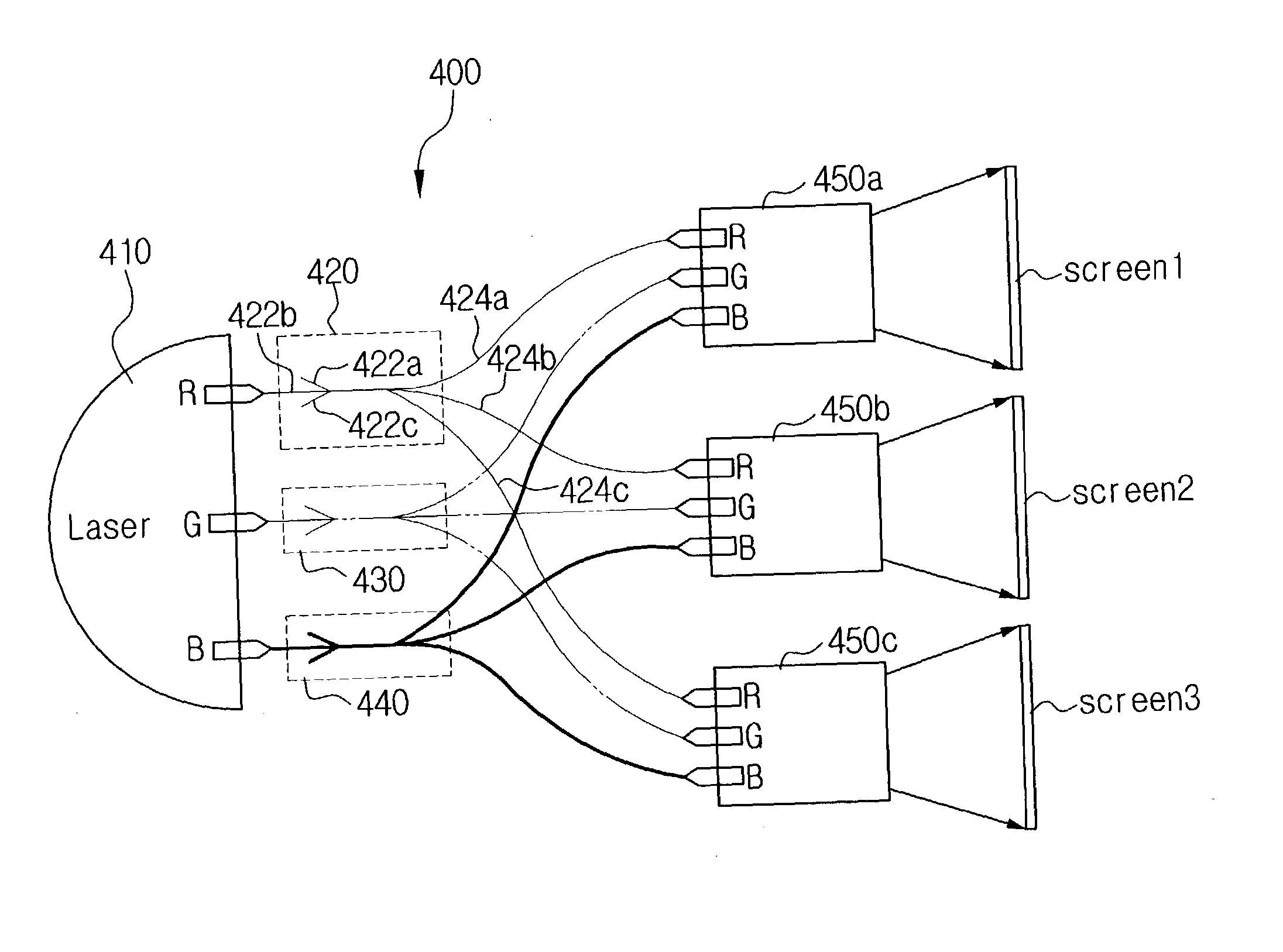
A light coupling device and an image projection apparatus using the same, wherein photoconductive media of the light coupling device include optical fibers that transmit light. Each light coupling device has at least two input terminals, at least two output terminals, and a connector connecting the input and output terminals, wherein the connector forms at least one light path. The light coupling device receives and divides respective R, G, and B monochromatic light beams. By connecting a light source with multiple optical instruments via the light coupling devices, images can be projected on multiple screens. Further, by using optical fibers to transmit light beams, the size of image instruments is minimized and light loss is reduced.

Description

[0001] This application claims priority to Korean Patent Application No. 2002-19300, filed Apr. 9, 2002, which is incorporated herein by reference in its entirety.[0002] 1. Field of the Invention[0003] The present invention relates to a light coupling device and an image projection apparatus using the same and, more particularly, to a light coupling device and an image projection apparatus using the same, which employ optical fibers to project red, green, and blue (R, G, and B) laser beams onto multiple screens, respectively.[0004] 2. Description of the Related Art[0005] A projector is an image projection apparatus showing images by projecting inputted image signals onto screens. Such an image projection apparatus is mainly employed to give presentations in conference rooms or to implement projectors in theaters and home theater systems.[0006] Prior art methods for implementing a large screen magnify images through lenses and project images onto screens, wherein the images appear on...

Claims


Application Information

Patent Timeline
IPC IPC(8): H04N9/31G02B27/00
CPCH04N9/3105H04N9/3197H04N9/315H04N9/3129G02B27/00
Inventor DHO, SANG-WHOE
Owner SAMSUNG ELECTRONICS CO LTD
Learn More