Aerosol generator for drug formulation

a technology of generators and aerosols, applied in the direction of respirators, transportation and packaging, packaging, etc., can solve the problems of patient inability to generate sufficient flow to activate the unit, patient may not inhale a full dose of medication, and inspiration varies

Inactive Publication Date: 2003-12-18
PHILIP MORRIS USA INC
View PDF23 Cites 29 Cited by
  • Summary
  • Abstract
  • Description
  • Claims
  • Application Information

AI Technical Summary

Benefits of technology

[0012] According to the second embodiment, the aerosol generator can include a housing and a cap slidably attached to the housing, the cap including the mouthpiece at one end thereof, the cap being slidable from an off position at which aerosol is prevented from being delivered to the interior of the mouthpiece to an aerosol delivery position at which the aerosol generating system is in a breath actuation mode wherein the user can obtain a dose of aerosol by inhaling on the outlet. Preferably, the aerosol generator comprises a hand-held inhaler and the aerosol generating system comprises a capillary sized flow passage and a heater arranged to volatilize liquid in the flow passage so as to produce the aerosol in the interior of the mouthpiece. The aerosol generator can further comprise a dispensing member and a metering chamber, the metering chamber comprising a recess and an elastomeric wall covering the recess, the dispensing member being movable from a first position relative to the elastomeric wall to a second position at which the elastomeric wall is deformed into the recess, the metering chamber providing fluid communication between a source of fluid and the flow passage, and the dispensing member being movable in a manner which provides a substantially constant flow rate of the fluid in the flow passage.

Problems solved by technology

A problem with such systems is that inspiration varies from person to person and some patients are unable to generate sufficient flow to activate the unit.
Although attempts have been made to improve breath actuation systems, detection is still based on air flow generated by the patient with the result that the patient inhales a volume of air before delivery of the aerosol occurs.
As a result, the patient may not inhale a full dose of medication.

Method used


Image

  • Aerosol generator for drug formulation
  • Aerosol generator for drug formulation
  • Aerosol generator for drug formulation

Examples


Embodiment Construction

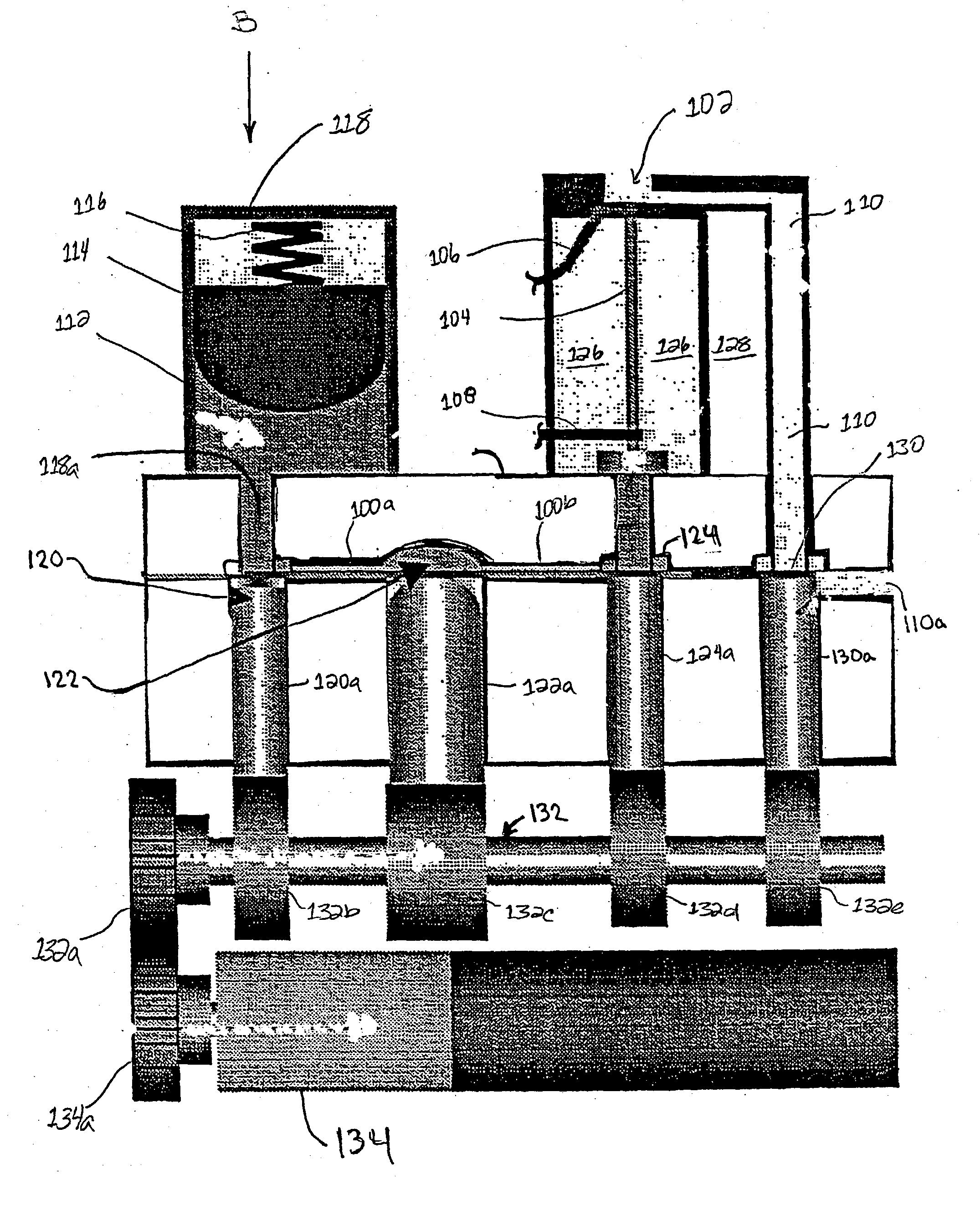
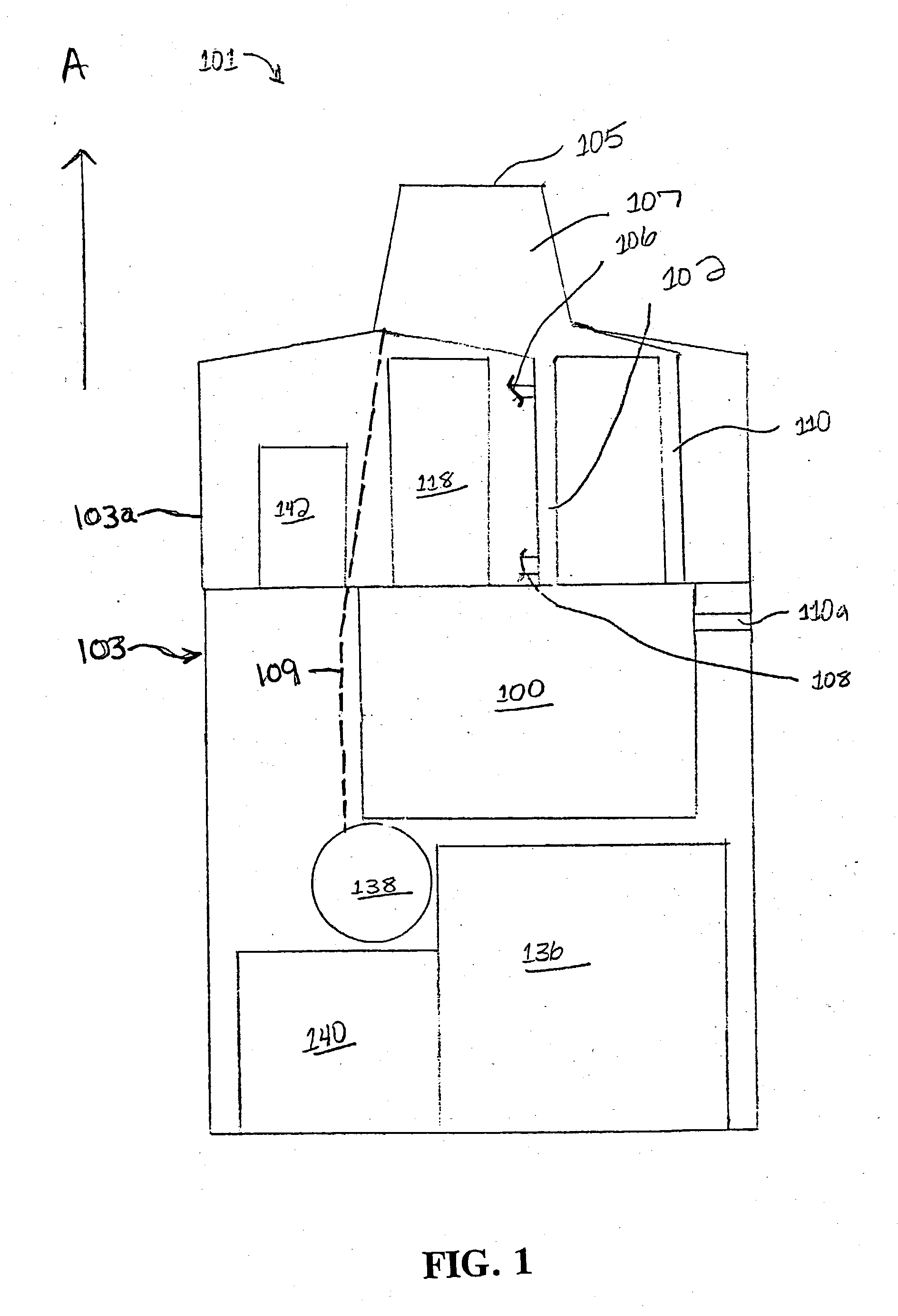
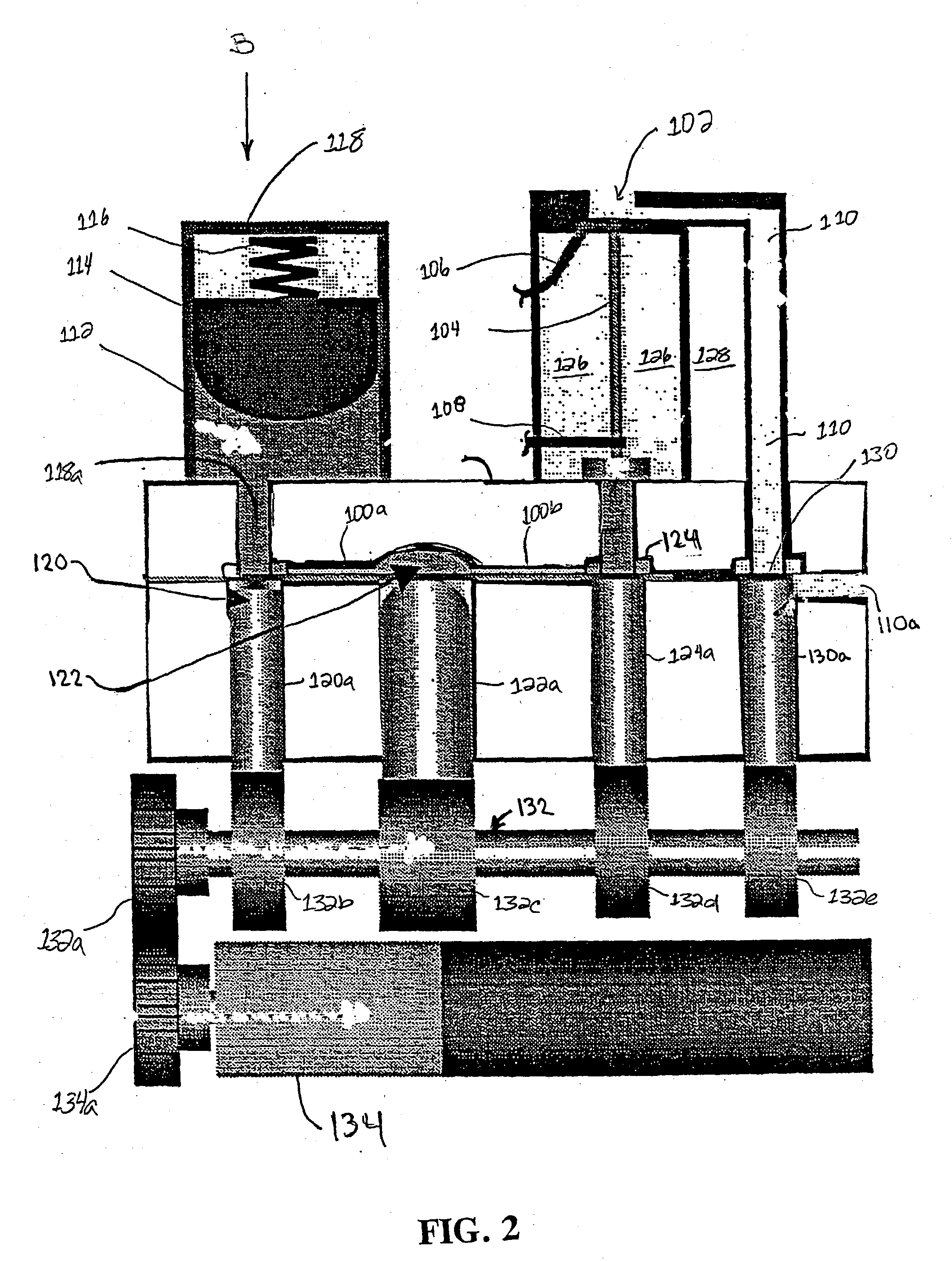
[0028] As an overview, the present invention provides an aerosol generator such as a hand-held inhaler and method of delivering aerosol to a user inhaling on an outlet of a mouthpiece when a pressure drop is detected within the mouthpiece. A medicated fluid passing through a capillary passage is heated sufficiently to vaporize the fluid and form the aerosol by condensation of the vaporized fluid as it admixes with air. Air is supplied to the mouthpiece through an air passage which is initially closed during detection of the pressure drop. A metering chamber allows consistent delivery of precise doses of fluid to the capillary passage. The pressure drop is detected before air is supplied to the mouthpiece with the result that the aerosol can be delivered quickly to the user as the user begins to inhale on the mouthpiece. The quick delivery of aerosol provides more efficient use of the user's lung capacity.

[0029] An aerosol generator in accordance with a preferred embodiment of the pr...


PUM


Abstract

An aerosol generator such as a hand-held inhaler and method of delivering aerosol to a user inhaling on an outlet of a mouthpiece when a pressure drop is detected within the mouthpiece. A medicated fluid passing through a capillary passage is heated sufficiently to vaporize the fluid and form the aerosol by condensation of the vaporized fluid as it admixes with air. Air is supplied to the mouthpiece through an air passage which is initially closed during detection of the pressure drop. A metering chamber allows consistent delivery of precise doses of fluid to the capillary passage. The pressure drop is detected before air is supplied to the mouthpiece with the result that the aerosol can be quickly delivered to the user as the user begins to inhale on the mouthpiece. The quick delivery of aerosol provides more efficient use of the user's lung capacity.

Description

[0001] 1. Field of the Invention[0002] The present invention relates generally to aerosol generation. More specifically, the present invention relates to an aerosol generator which provides controlled doses of medicament to a patient during use.[0003] 2. Description of Related Art[0004] Metered dose inhalers for delivering aerosol medication for inhalation by a patient are disclosed in U.S. Pat. Nos. 5,487,378; 5,522,378; 5,622,162; 5,794,612; 5,839,430; 5,894,841; and 6,152,130. Some inhalers use the propulsive force of a propellant system such as a mixture of liquified chlorofluorocarbons. Other inhalers use an ultrasonic nebulizer system to atomize a liquid in a carrier gas stream or a burst of inspired air to fluidize and draw a dose of powder into the bronchial tract. Commonly owned U.S. Pat. Nos. 5,743,251 and 6,234,167 disclose aerosol generators wherein a liquid formulation is vaporized to form an inhalation aerosol.[0005] In order to trigger delivery of aerosol from an inha...

Claims


Application Information

Patent Timeline
Patent Type & Authority Applications(United States)
IPC IPC(8): A61MA61M1/00A61M11/00A61M11/04A61M15/00A61M16/00B05B12/08
CPCA61M11/041B05B12/08A61M15/0091A61M15/00A61M11/005B05B12/12A61M15/025A61M15/008A61M15/0081A61M15/0083A61M15/0093A61M15/0096
Inventor NICHOLS, WALTER A.BROOKMAN, DONALD L.GROLLIMUND, GARY E.SMITH, ULYSSES
Owner PHILIP MORRIS USA INC
Why Eureka
Try Eureka