Electrical machine having a rotor specially adapted to high speeds

a technology of electric traction motors and rotors, which is applied in the direction of dynamo-electric machines, magnetic circuit rotating parts, and magnetic circuit shapes/forms/construction, etc., can solve the problems of mechanical behavior, problems such as the problem of installing electric traction motors in the wheels of private vehicles, and the mechanical behavior of magnets

Inactive Publication Date: 2004-01-08
CONCEPTION & DEV MICHELIN SA
View PDF17 Cites 75 Cited by
  • Summary
  • Abstract
  • Description
  • Claims
  • Application Information

AI Technical Summary

Benefits of technology

[0017] Thus, the receiver of each magnet is closed off radially on the outer side. This allows much higher speeds of rotation to be achieved without damaging the magnets. It should be noted that pole pieces are preferably formed by a stack, in the axial direction, of ferromagnetic base sheets cut to the desired shape. All of the sheets are disposed substantially perpendicular to the axis of the shaft.

Problems solved by technology

These two requirements (high power level, and low weight and bulk) make it very problematic to install electric traction motors in the wheels of private vehicles without a radical improvement in the ratio of weight to power of the electrical machines currently available on the market.
However, increasing the speed of rotation of an electrical rotating machine poses numerous problems for the mechanical behavior, and these are particularly difficult if the intention is to keep the weight and bulk of the electrical rotating machine as small as possible.
If the speed of rotation is increased further, problems arise with the mechanical behavior of the magnets.
The radially outer end thereof is at risk of breaking up.

Method used


Image

  • Electrical machine having a rotor specially adapted to high speeds
  • Electrical machine having a rotor specially adapted to high speeds
  • Electrical machine having a rotor specially adapted to high speeds

Examples


Embodiment Construction

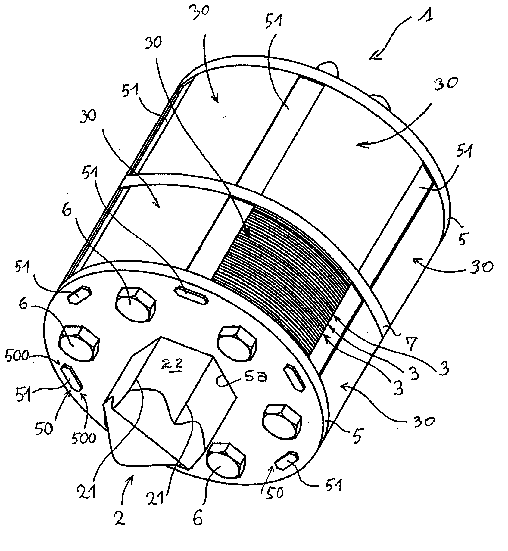
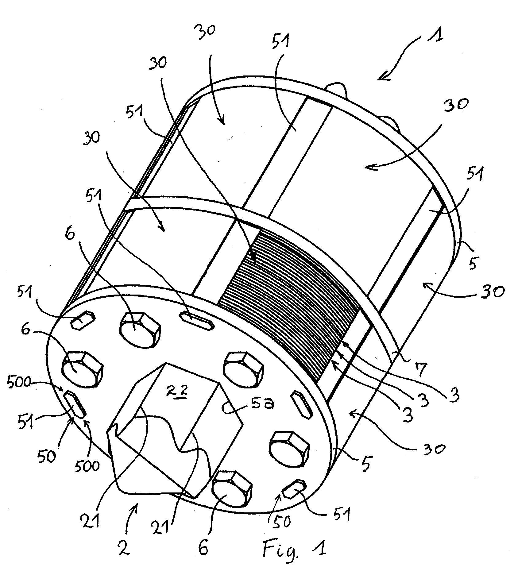
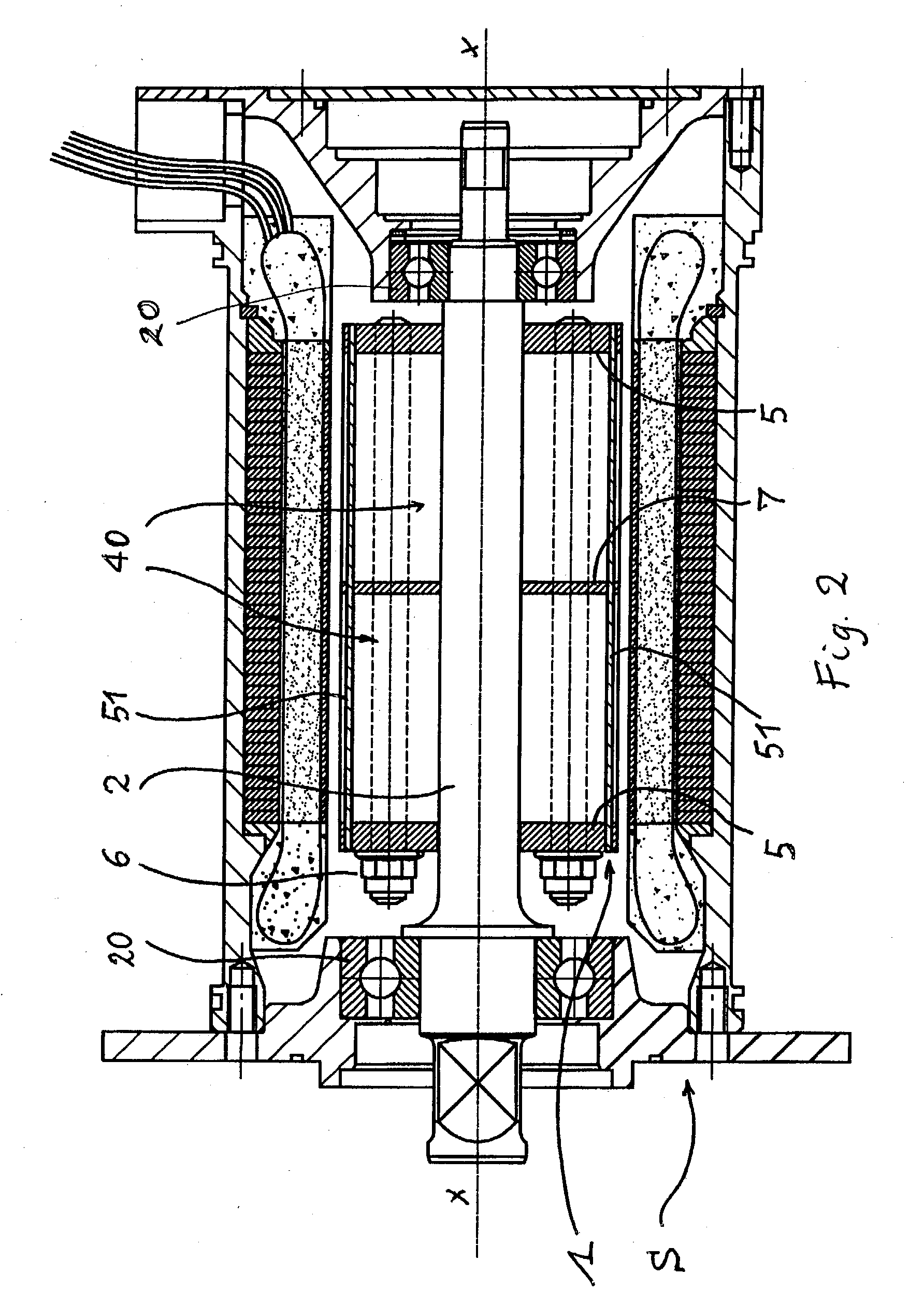
[0026] In FIGS. 1 to 3, there is illustrated a six-pole machine having a stator S (shown in FIG. 2) and a rotor 1, with a shaft 2 resting on bearings 20. At least an outer casing of the shaft 2, or the shaft in its entirety, is made of non-magnetic material. The rotor 1 includes a stack of ferromagnetic sheets 3, forming, as shown, six pole pieces 30. Each sheet 3 is substantially perpendicular to the axis of the shaft. It should be noted that the invention is also useful in the case of solid (not laminated) pole pieces.

[0027] Axially adjacent either end of the shaft 2 there is shown a lateral flange 5 (preferably made from non-magnetic material) located on either side of the pole pieces 30. Also shown is an optional intermediate plate 7 (preferably made from non-magnetic material). Each lateral flange 5 and, where applicable, each intermediate plate 7 has a central recess 5a. In the non-restrictive example described here, the central recess is polygonal in shape. The shape of the r...


PUM


Abstract

An electrical rotating machine having a rotor comprising a shaft made from nonmagnetic material, a plurality of pole pieces made from magnetic material and surrounding the shaft, with permanent magnets fixed in receivers by wedges cooperating with the pole pieces to block radially outward movement of the magnets.

Description

[0001] 1. The Field of the Invention[0002] The invention relates to electrical rotating machines wherein the rotor has permanent magnets. More particularly, the invention relates to machines in which the magnets are disposed in recesses in the rotor. The electrical machines in question are commonly called embedded magnet machines. This principle of arrangement for the rotor is widely applied to brushless synchronous machines with flux concentration.[0003] 2. The Related Art[0004] The size of an electrical rotating machine depends on its nominal torque. The higher the torque a motor is capable of delivering, the more bulky the electric motor, all other things being equal. There are, however, applications for which it is desirable to obtain both high power levels and a highly compact construction of the motor at the same time. To give just one concrete example, when the intention is to install electric traction motors in the wheels of automotive vehicles, it is desirable to be able to...

Claims


Application Information

Patent Timeline
Patent Type & Authority Applications(United States)
IPC IPC(8): H02K21/14H02K1/27
CPCH02K1/2773
Inventor LAURENT, DANIELPEGORARO, GIANCARLO
Owner CONCEPTION & DEV MICHELIN SA
Why Eureka
Try Eureka