Ring gear

a technology of ring gear and ring base, which is applied in the direction of gear teeth, hoisting equipment, other domestic objects, etc., can solve the problems of limiting the design of the rounding of the tooth base, and the inability to create longitudinally cambered tooth flanks

Inactive Publication Date: 2004-02-12
ROBERT BOSCH GMBH
View PDF13 Cites 4 Cited by
  • Summary
  • Abstract
  • Description
  • Claims
  • Application Information

AI Technical Summary

Problems solved by technology

However, longitudinally cambered tooth flanks cannot be created by this process.
In typical rolling methods, such as by means of milling or planing, longitudinally cambered tooth flanks can indeed be produced, but limits are placed on the design of the rounding of the tooth base.

Method used


Image

  • Ring gear
  • Ring gear
  • Ring gear

Examples


Embodiment Construction

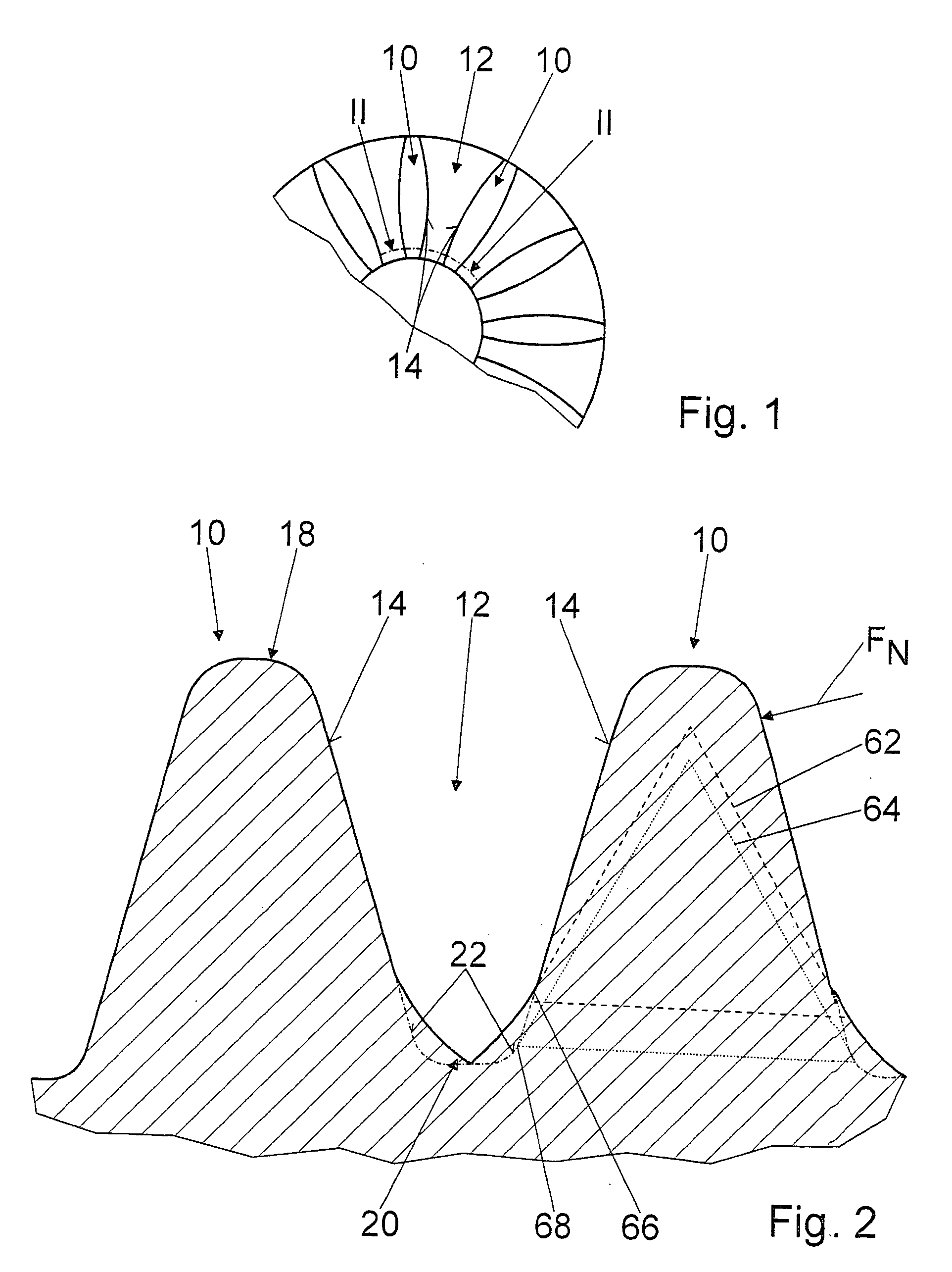
[0026] FIG. 1 shows a detail of a schematic plan view of a ring gear of the invention, with teeth 10 and tooth gaps 12; the teeth 10 can be brought into engagement with a corresponding pinion, not shown in detail here, by way of tooth flanks 14.

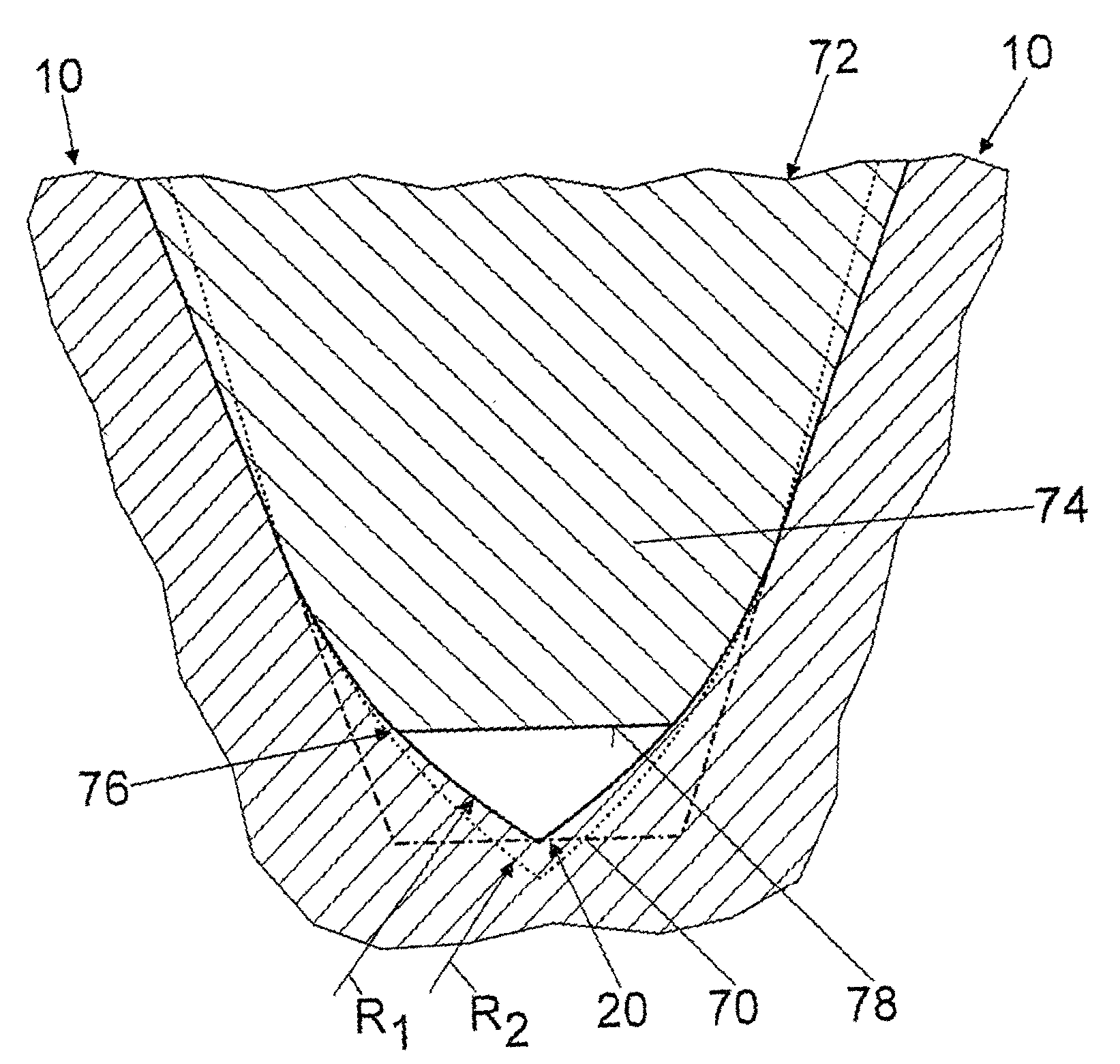
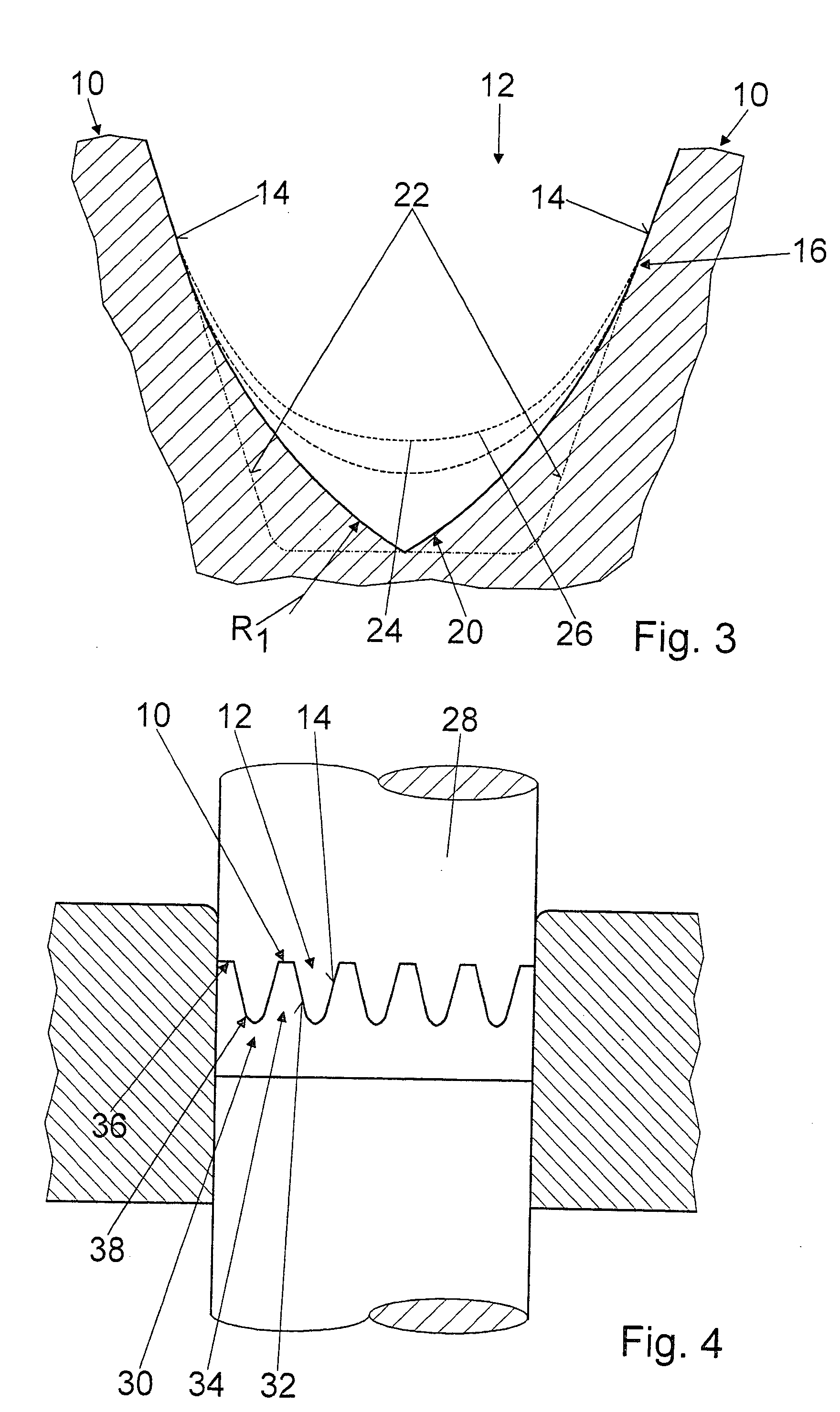
[0027] The tooth flanks 14, after a final engagement point 16 of the pinion, from the tooth head 18 toward the tooth base 20, compared to standard tooth flanks 22, are made to approximate a trochoid 24, 26, described by the pinion and projected into a normal section; specifically, the tooth gap 12 is embodied in the form of a pointed arch in cross section in the region of the tooth base 20 (FIGS. 2 and 3).

[0028] The trochoid 24 is described by a pinion with a rated tooth height, and the trochoid 26 is described by a pinion with a rated tooth height plus 0.1 mm. The tooth flanks 14, after the last engagement point 16 in the direction of the tooth base 20, have a radius R.sub.1 of approximately 1.6 mm and before the engagement point 16 from the...


PUM

PropertyMeasurementUnit
heightaaaaaaaaaa
radius R1aaaaaaaaaa
radius R2aaaaaaaaaa

Abstract

The invention is based on a ring gear with teeth (10) and tooth gaps (12), in which the teeth (10) can be brought via tooth flanks (14) into engagement with a corresponding pinion. It is proposed that the tooth flanks (14), after a final engagement point (16) of the pinion, from the tooth head (18) toward the tooth base (20), compared to standard tooth flanks (22), are made to approximate a trochoid (24, 26), described by the pinion and projected into a normal section.

Description

PRIOR ART[0001] The invention is based in particular on a ring gear as generically defined by the preamble to claim 1.[0002] In principle, the goal is to furnish ring gears and pinions that correspond with the ring gears that assure a long service life and quiet meshing.[0003] In production, the goal is to replace metal-cutting production methods that as a rule are cost-intensive, with economical noncutting production methods, and sintering gains high significance.[0004] A stamping tool that can be used for sintering has a negative form of a set of teeth of the ring gear or pinion, as applicable, to be made, and is advantageously produced with an electrode.[0005] Suitable electrodes are typically produced in a rolling process on a bevel-gear toothing, or are wire-eroded in a numerical copying process. In wire erosion, an arbitrary design for rounding out of the tooth base is possible. However, longitudinally cambered tooth flanks cannot be created by this process.[0006] In typical r...

Claims


Application Information

Patent Timeline
Patent Type & Authority Applications(United States)
IPC IPC(8): B23F5/20B22F5/08B23F1/06F16H55/08F16H55/17
CPCB22F5/08B23F1/06Y10T74/19963Y10T29/49462Y10T74/19958F16H55/0846
Inventor BARTH, WALTER
Owner ROBERT BOSCH GMBH
Why Eureka
Try Eureka