
De-embedment of optical component characteristics and calibration of optical receivers using rayleigh backscatter

a technology of optical components and characteristics, applied in the field of deeming optical components, can solve the problems of difficult to determine the difference in the level of rbs from one side of the optical component to the other, and the technique cannot be used to directly measure the characteristics of optical components such as connector loss

Inactive Publication Date: 2004-02-26
AGILENT TECH INC
View PDF3 Cites 6 Cited by
  • Summary
  • Abstract
  • Description
  • Claims
  • Application Information

AI Technical Summary

Problems solved by technology

In actuality, however, some loss in signal strength will be incurred.
Unfortunately, using interferometic measurement techniques, the detected RBS has a noise like behavior that exists at all input power levels This noise like behavior makes it difficult to determine the difference in the level of RBS from one side of the optical component to the other.
However, these techniques cannot be used to directly measure optical component characteristics such as connector loss.
Another challenge in making RBS measurements using interferometic measurement techniques is to ensure that the magnitude response of the photoreceiver is flat over the desired frequency range.
Non-linearity in the photoreceiver response results in variations in the photoreceiver output that prevent an accurate measurement of the RBS levels.
Such broadening can make it very difficult to detect individual, closely-spaced reflections
Because of the above difficulties in making RBS measurements, optical components characteristics measured based on RBS are sometimes inaccurate.
As a result, the optical component characteristics can be incorrectly de-embedded from the optical device measurements.

Method used


Image

  • De-embedment of optical component characteristics and calibration of optical receivers using rayleigh backscatter
  • De-embedment of optical component characteristics and calibration of optical receivers using rayleigh backscatter
  • De-embedment of optical component characteristics and calibration of optical receivers using rayleigh backscatter

Examples


Embodiment Construction

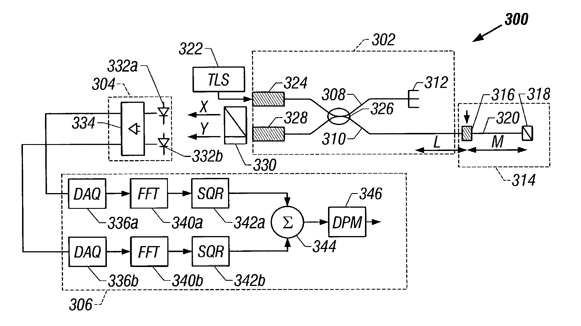
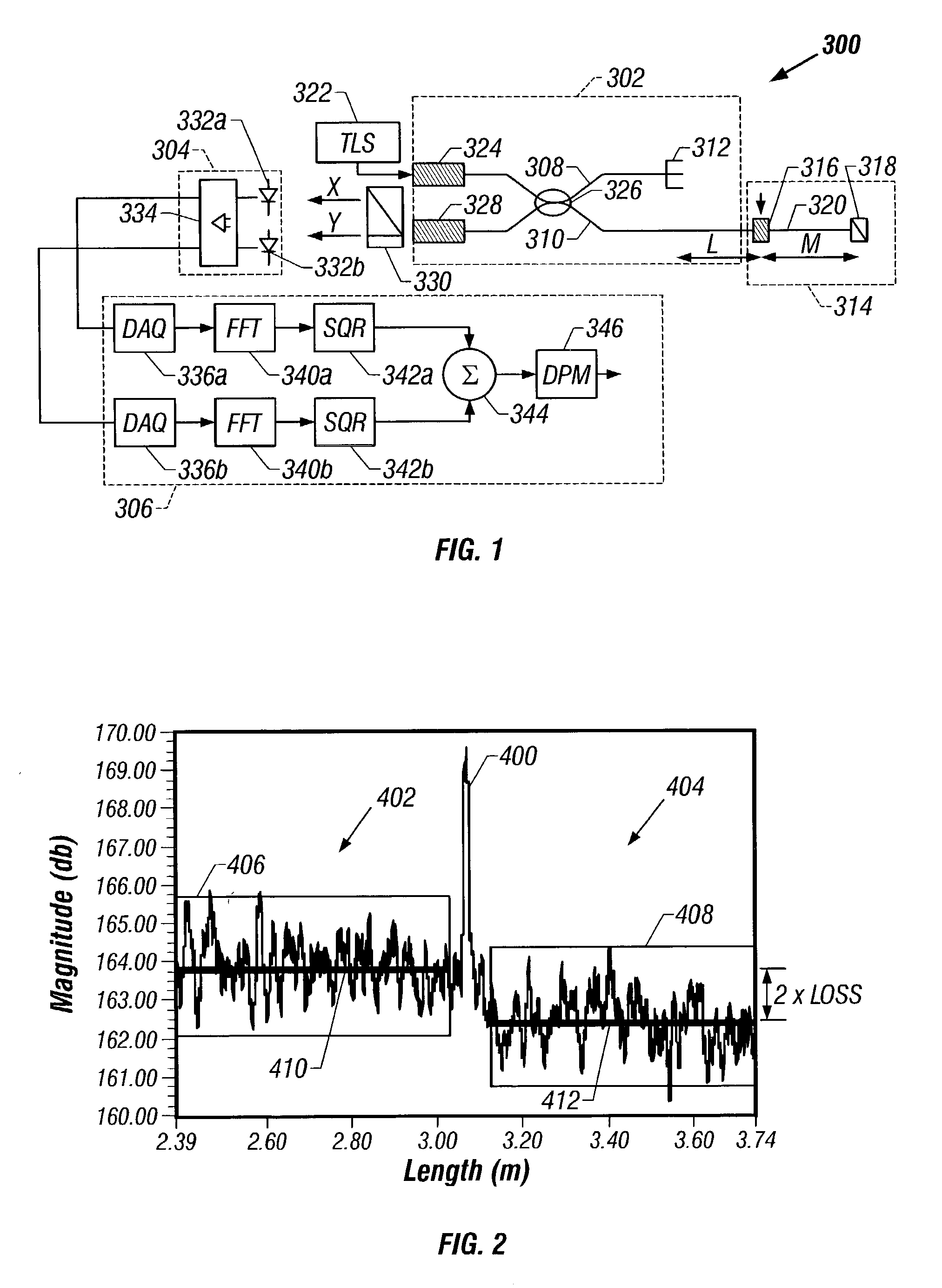
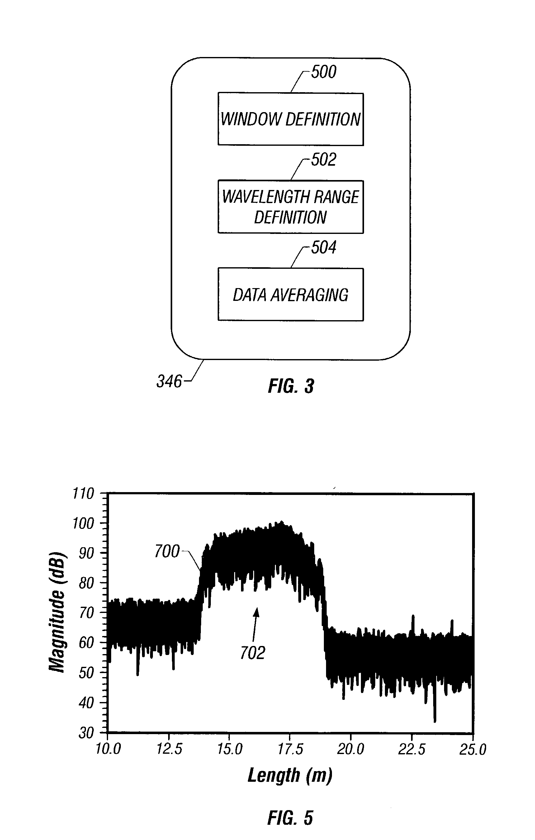
[0026] Embodiments of the invention provide a system and method for making more accurate optical component characteristic measurements using RBS The optical component characteristics can then be de-embedded from optical device measurements to provide a more precise analysis of the optical device. The accuracy of the optical component characteristic measurements can be improved by improving the accuracy of the RBS measurements. The accuracy of the RBS measurements, in turn, can be improved by frequency domain averaging of the RBS within a predefined window on both sides of the optical component. The averaged RBS may then be used to more precisely determine the RBS level on either side of the optical component In some embodiments of the invention, the averaging windows can be expanded in order to increase the number of data points available for averaging. In some embodiments of the invention, the number of data points available for averaging can be increased by expanding the sweep wav...


PUM


Abstract

Method and system are disclosed for de-embedding optical component characteristics from optical device measurements In particular, the invention uses frequency domain averaging of the RBS on both sides of an optical component to determine one or more of its optical characteristics. Where the RBS has a slope (e.g., as in the case of a lossy fiber), a frequency domain least square fit can be used to determine the optical component characteristics. In addition, the invention uses a reference DUT to correct for variations in the frequency response of the photoreceiver A reference interferometer is used in the invention to correct for sweep non-linearity of the TLS. The optical component characteristics are then de-embedded from optical device measurements to provide a more precise analysis of the optical device.

Description

[0001] 1. Technical Field of the Invention[0002] The present invention is related to the de-embedding of optical component characteristics from optical device measurements and, in particular, to a method and system for de-embedding the optical component characteristics using Rayleigh backscatter.[0003] 2. Background of the Invention[0004] Ideally, an optical signal entering one side of an optical component such as a connector or splice emerges from the other side at the same signal level. In actuality, however, some loss in signal strength will be incurred. Therefore, when analyzing an optical device, it is important to first de-embed the signal loss or other characteristics of any optical components that may be present.[0005] Rayleigh backscatter (RBS) measurements can be used for de-embedding optical component characteristics such as signal loss. When measuring RBS, the level of RBS can be expressed in terms of the reflectivity RRBS of the optical fiber as follows.R.sub.RBS=S.mult...

Claims


Application Information

Patent Timeline
IPC IPC(8): G01J1/08G01M11/00
CPCG01J1/08G01N2021/4709G01M11/3109
Inventor MOTAMEDI, ALI R.BANEY, DOUGLAS M.
Owner AGILENT TECH INC
Learn More