Cable cutter

a cable cutter and cable technology, applied in the field of cable cutters, can solve the problems of inappropriate or ineffective cutting of cables, inability to effectively and efficiently cut acsr cables, etc., and achieve the effect of efficiently and effectively cutting acsr cables

Inactive Publication Date: 2004-03-04
TEXTRON INNOVATIONS
View PDF0 Cites 13 Cited by
  • Summary
  • Abstract
  • Description
  • Claims
  • Application Information

AI Technical Summary

Benefits of technology

[0005] A primary object of the invention is to provide a tool which is capable efficiently and effectively cutting ACSR cable using manual force.
[0006] An object of the invention is to provide a tool which is capable of efficiently and effectively cutting cables made of softer material, such as aluminum or copper, using manual force, and which is capable of efficiently and effectively cutting cables made of harder, material, such as steel, using manual force.
[0011] Still another object of the invention is to provide a tool having cutting configurations which allow for the outer aluminum stranded configuration of ACSR cable to be cut prior to the harder central steel core of the ACSR cable being cut, which reduces the required force to make the cut.
[0012] Another object of the invention is to provide a tool having cutting configurations which do not allow the harder central steel core of ACSR cable to be cut by the sharp edges of the blade members, which are designed to cut the softer outer aluminum stranded configuration of the ACSR cable, thus preventing the dulling of the sharp edges of the blade members which reduces the wear life of the sharp edges.

Problems solved by technology

It has been found, however, that these prior art cable cutters do not adequately cut cables formed of materials harder than copper or aluminum, such as steel.
Thus, persons using such cable cutters may also find it necessary to have another cable cutter which is specifically designed for cutting steel.
Both of the prior art cable cutters discussed above are inadequate for cutting ACSR cable; the cable cutters made for aluminum and / or copper are inappropriate or ineffective in cutting steel while the cable cutters made for steel would crush or otherwise damage copper or aluminum cables beyond the point at which the cut ends are useful.

Method used


Image

  • Cable cutter
  • Cable cutter
  • Cable cutter

Examples


Embodiment Construction

[0018] While this invention may be susceptible to embodiment in different forms, there is shown in the drawings and will be described herein in detail, a specific embodiment with the understanding that the present disclosure is to be considered an exemplification of the principles of the invention, and is not intended to limit the invention to that as illustrated and described herein.

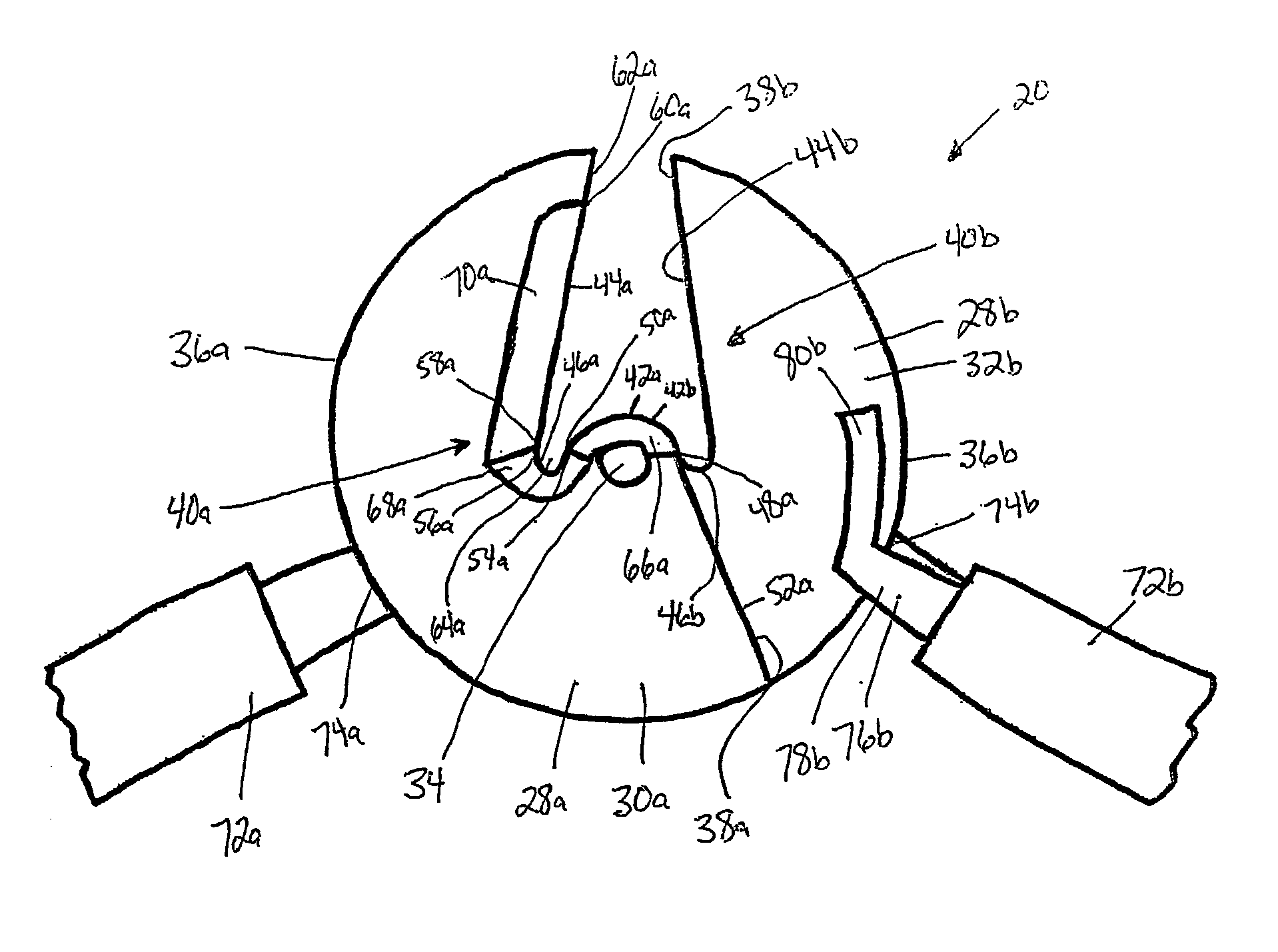
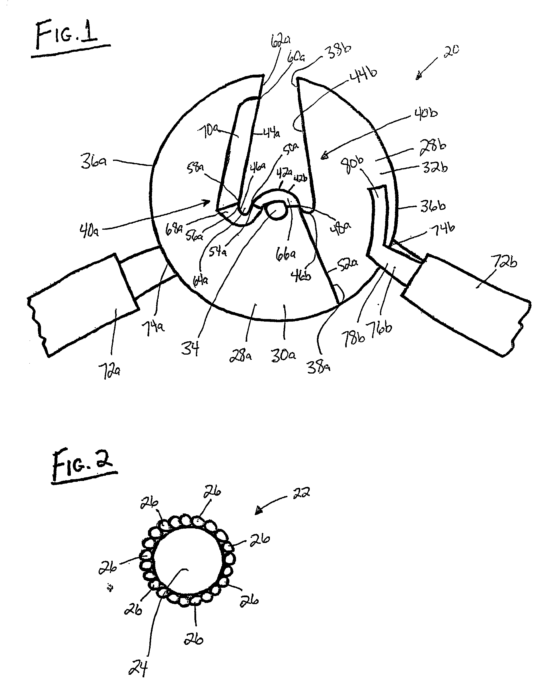
[0019] A tool 20 which is used to cut a workpiece 22, such as cable, is provided and is illustrated in FIG. 1. The tool 20 is preferably used to cut aluminum cable steel reinforced ("ACSR") cable 22, which is illustrated in FIG. 2, but can also be used to cut cables made of soft material, such as aluminum or copper, or cables of hard material, such as steel.

[0020] As shown in FIG. 2, ACSR cable 22 typically includes a single strand center core 24 formed of steel and an outer stranded cable configuration 26 formed of a plurality of strands of aluminum. The harder central steel core 24 is used as a reinfo...


PUM

PropertyMeasurementUnit
radiusaaaaaaaaaa
sizeaaaaaaaaaa
hardnessaaaaaaaaaa

Abstract

A tool for use in cutting cable, preferably ACSR cable, includes first and second blades having cutting configurations. The first and second blades are pivotally connected and a handle are attached to each blade. Movement of the handles rotates the blades about the pivot point. Cable positioned between the cutting configurations is systematically cut by the cutting configurations as the blades are rotated toward each other. Each cutting configuration includes first and second sharp edges and a blunt edge positioned therebetween which defines a concave recess. The first and second sharp edges are used to cut the aluminum strands surrounding the steel cable. During the cutting of the aluminum strands, the steel portion of the cable is urged into the concave recess defined by the blunt edges. The steel cable is then sheared using the blunt edges.

Description

[0001] The present invention relates to a cable cutter for cutting cables. More specifically, the present invention relates to a cable cutter having a blade configuration which enables the cable cutter to efficiently and effectively cut aluminum cable steel reinforced ("ACSR") cable.[0002] Cables commonly used in the electrical industry are typically formed of copper and / or aluminum and may be of the type which are solid or stranded. Prior art cable cutters, with the application of sufficient manual force, serve adequately to cut the copper and / or aluminum cables. It has been found, however, that these prior art cable cutters do not adequately cut cables formed of materials harder than copper or aluminum, such as steel. Thus, persons using such cable cutters may also find it necessary to have another cable cutter which is specifically designed for cutting steel.[0003] The use of ACSR cable has been increasing in the electrical industry. ACSR cable includes one or more center reinfor...

Claims


Application Information

Patent Timeline
Patent Type & Authority Applications(United States)
IPC IPC(8): B23D29/02
CPCB23D29/023
Inventor STALDER, TERENCE G.
Owner TEXTRON INNOVATIONS
Why Eureka
Try Eureka