Transmission mechanism with a caseless differential mechanism

a differential mechanism and transmission mechanism technology, applied in mechanical devices, transportation and packaging, gear locks, etc., can solve the problems of complex, expensive and difficult to maintain the differential gear lock limiting mechanism used in the ar

Inactive Publication Date: 2004-03-18
XINJIANG SHENG SHENG
View PDF4 Cites 10 Cited by
  • Summary
  • Abstract
  • Description
  • Claims
  • Application Information

AI Technical Summary

Problems solved by technology

Because when an automotive vehicle encounters weaker roads, such as loose soil, foothill and the like, two wheels of the automotive vehicle at the same side may lose

Method used


Image

  • Transmission mechanism with a caseless differential mechanism
  • Transmission mechanism with a caseless differential mechanism
  • Transmission mechanism with a caseless differential mechanism

Examples


Embodiment Construction

[0018] The present invention will be further described below with reference to the drawings.

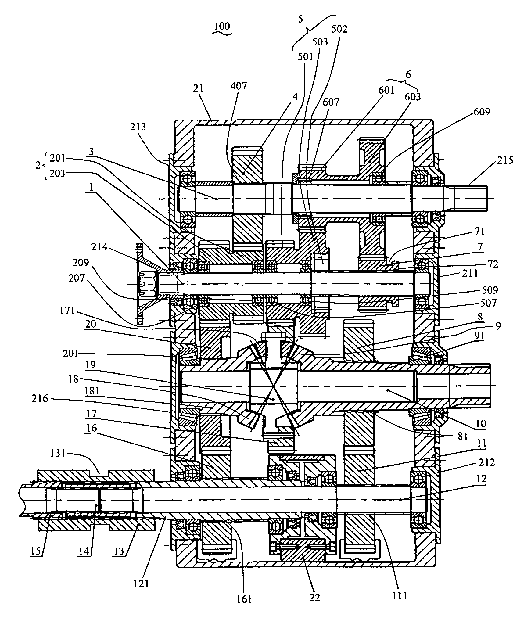
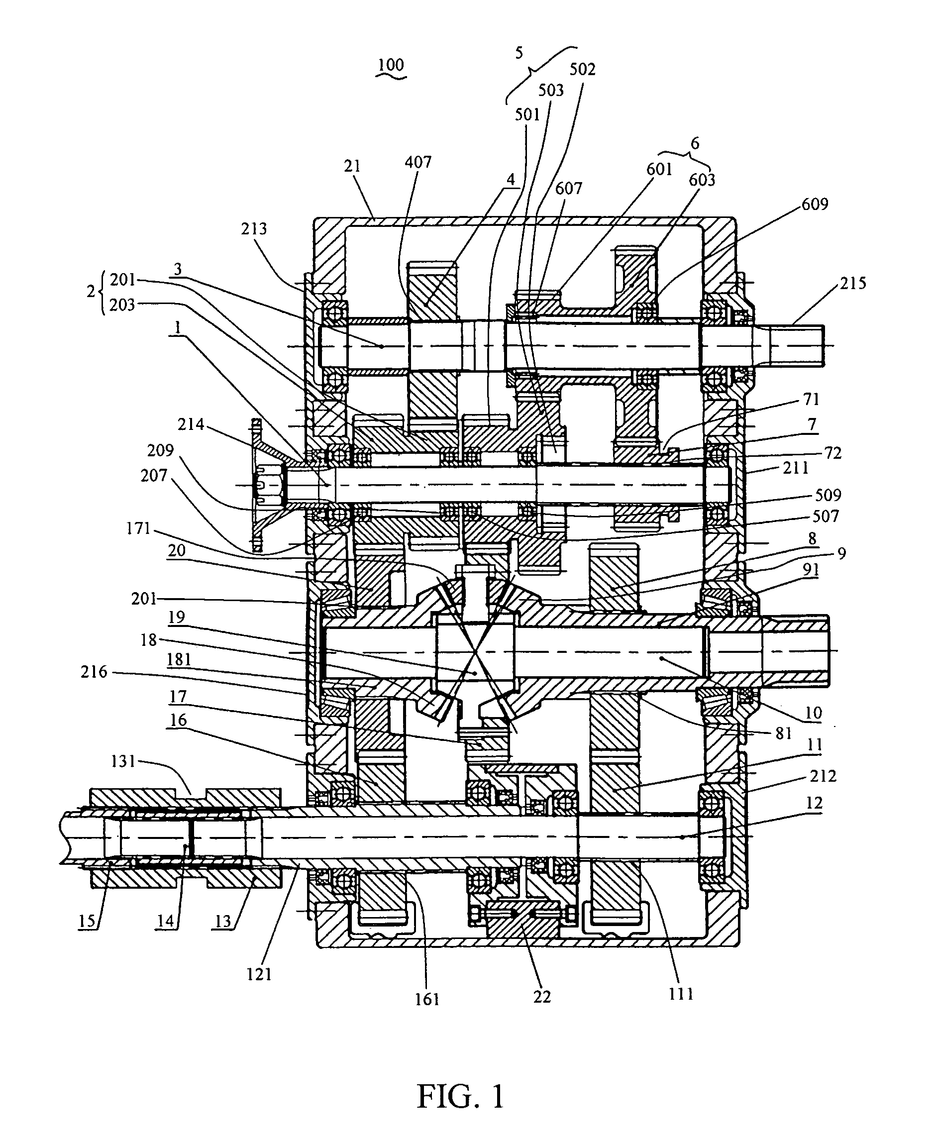
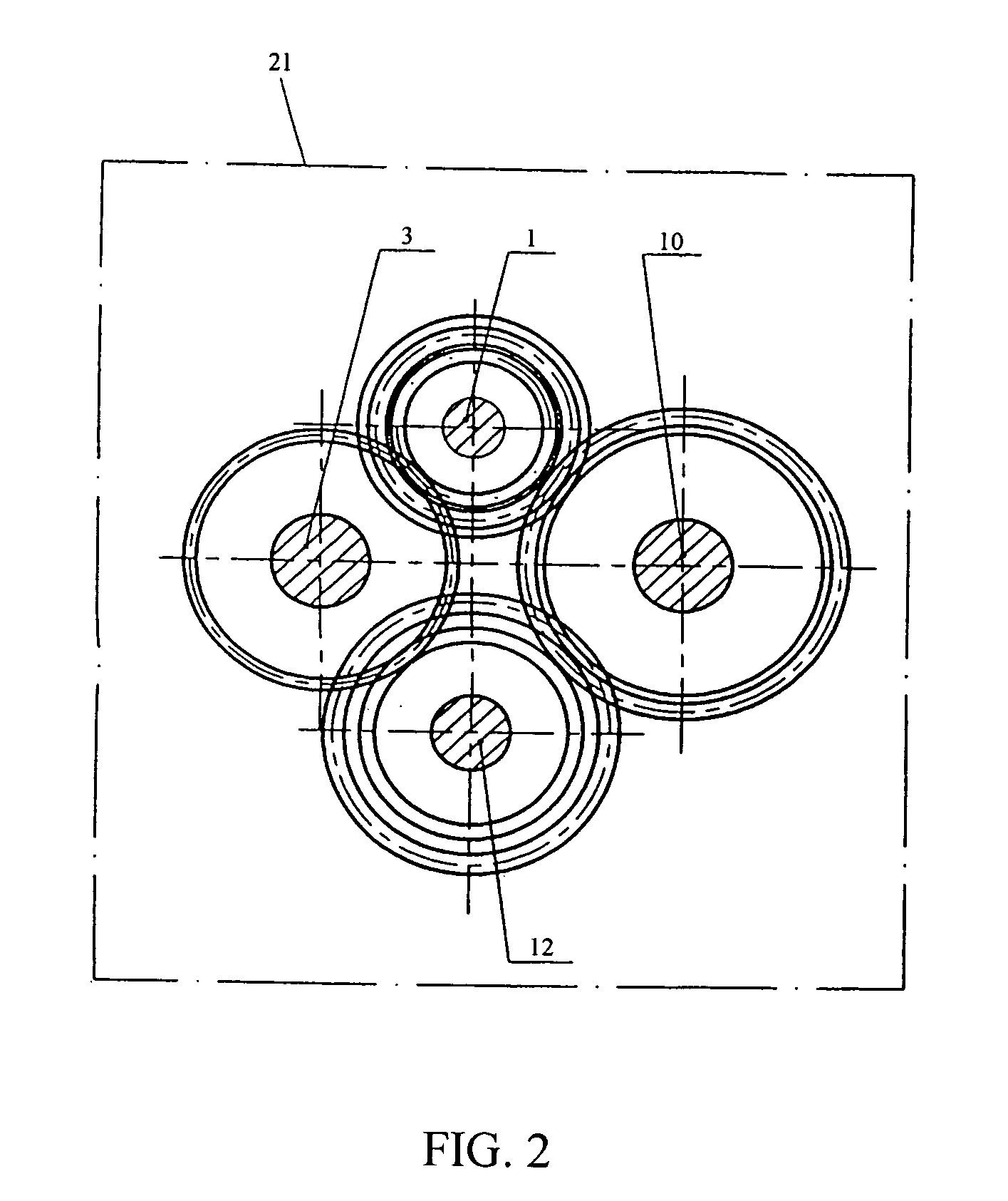
[0019] Referring to FIGS. 1 to 3, a transmission mechanism 100 of an automotive vehicle in accordance with the present invention includes a housing 21, a rear right wheel output shaft 3, a driving power input shaft 1, a core shaft 10, a front left wheel output shaft 14, a front right wheel output shaft 15, a propeller shaft 12, and a caseless differential mechanism 19 mounted at the right side of the housing 21 and including a right side bevel gear 9, a left side bevel gear 18 and a ring gear 17. The housing 21 has a first bearing bracket 211 disposed at the upper portion thereof, a second bearing bracket 212 disposed at the lower portion thereof, a third bearing bracket 213 disposed at the left portion thereof and a fourth bearing bracket 216 disposed at the right portion thereof.

[0020] The driving power input shaft 1 is connected with an engine (not shown) of the automotive vehicle via a fi...


PUM


Abstract

The present invention provides a transmission mechanism with a caseless differential mechanism for an automotive vehicle to drive four wheels instead of two differential mechanisms of the prior art disposed on the front axle and rear axle. The transmission mechanism of the invention is of a compact structure and a relatively less cost of manufacturing, and makes a clearance between the chassis of the automotive vehicle and the ground increased. The performance of the automotive vehicle equipped with the transmission mechanism of the invention can be improved.

Description

[0001] Chinese patent application CN 02 2 53903.4 filed Sep. 12, 2002.[0002] Not Applicable[0003] 1. Field of the Invention[0004] The present invention relates to a transmission mechanism of automotive vehicles, and more particularly to a transmission mechanism with a caseless differential mechanism.[0005] 2. Description of the Related Art[0006] Many transmission mechanisms with a differential gear lock limiting mechanism have been used in automotive vehicles. Because when an automotive vehicle encounters weaker roads, such as loose soil, foothill and the like, two wheels of the automotive vehicle at the same side may lose adhesions to the ground to cause skidding. The differential gear lock limiting mechanism can limit different rotating speeds of the two wheels up to locking the differential gear of the automotive vehicle. In this case, the driving side shafts of the two sides will be integrated, and the automotive vehicle can only be driven in line. Moreover, the differential gea...

Claims


Application Information

Patent Timeline
IPC IPC(8): B60K17/16B60K17/34B60K23/08F16H37/08F16H48/06
CPCB60K17/16B60K17/34Y10T74/19233F16H37/0813Y10T74/19316B60K23/0808F16H48/06
Inventor MA, WEIJINYANG, MINGXUEWANG, YUJIANGWANG, YINGPULIANG, BINFAN, YONGGEPAN, WENBINGAO, FENG
Owner XINJIANG SHENG SHENG
Why Eureka
Try Eureka