
Method and device for separation and concentration by evaporation of mixture with separation factor of approx.1

a technology of separation factor and separation device, which is applied in the direction of separation process, liquefaction, lighting and heating apparatus, etc., can solve the problems of increased no evidence has been provided as to whether or not the liquid holdup within the distillation apparatus can be reduced, and long start-up time. problems, to achieve the effect of reducing liquid holdup

Inactive Publication Date: 2004-04-01
ASANO
View PDF22 Cites 8 Cited by
  • Summary
  • Abstract
  • Description
  • Claims
  • Application Information

AI Technical Summary

Benefits of technology

[0019] The present invention takes the above factors into consideration, with an object of providing a separation and enrichment method and apparatus to minimize liquid holdup.
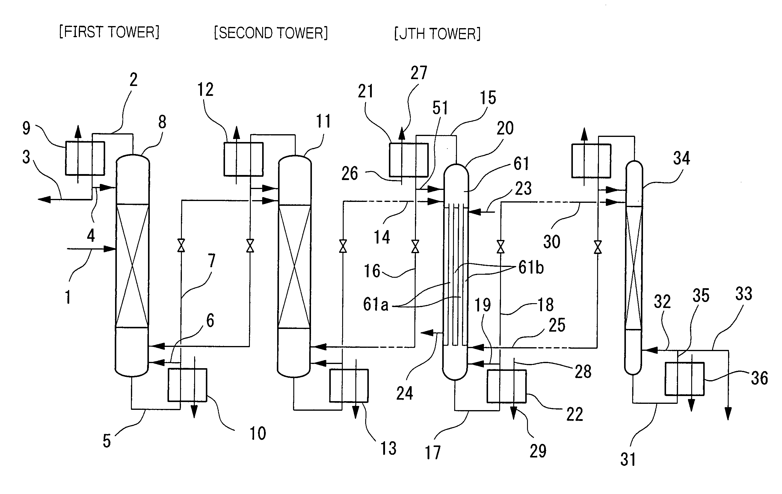
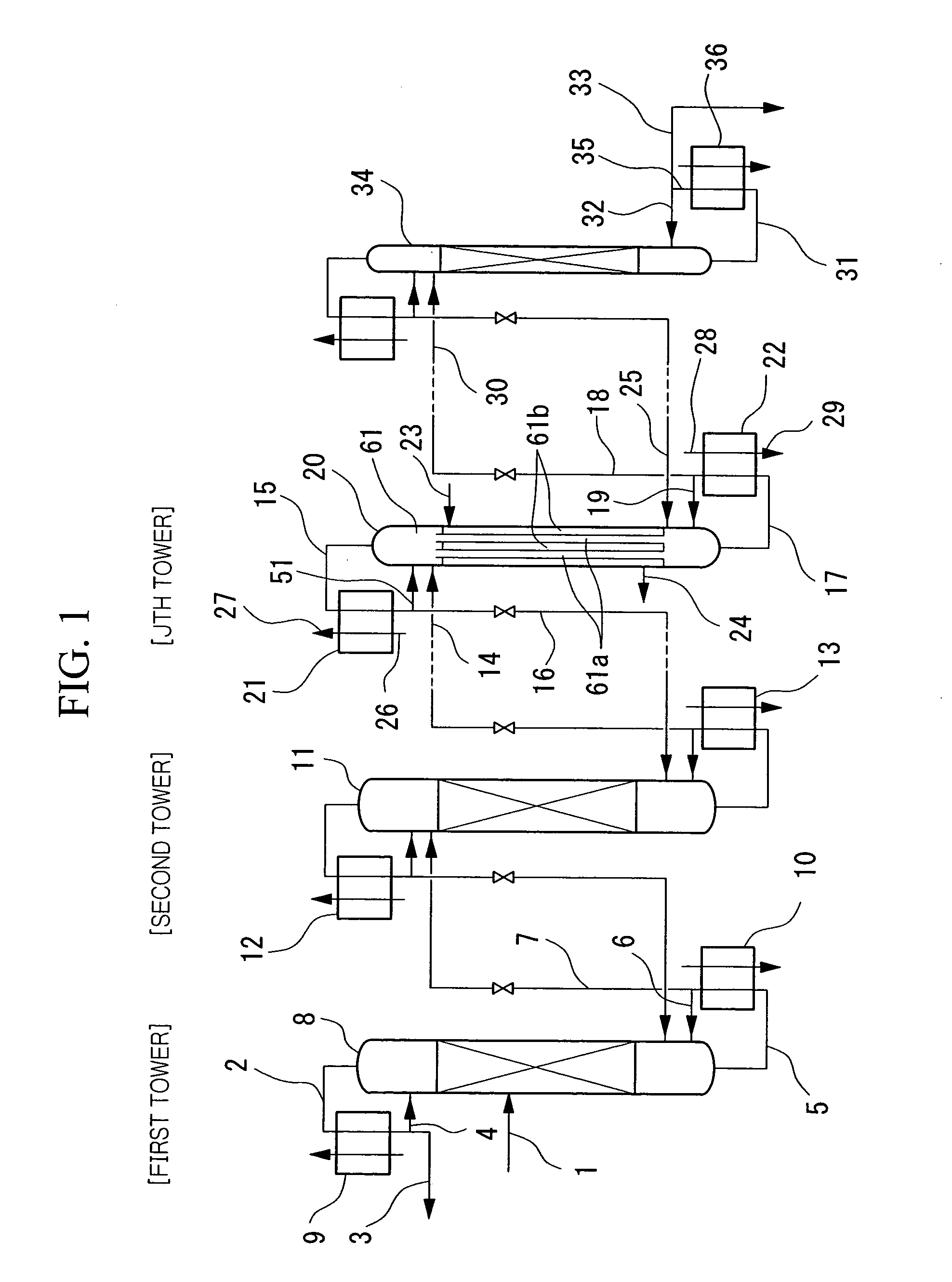
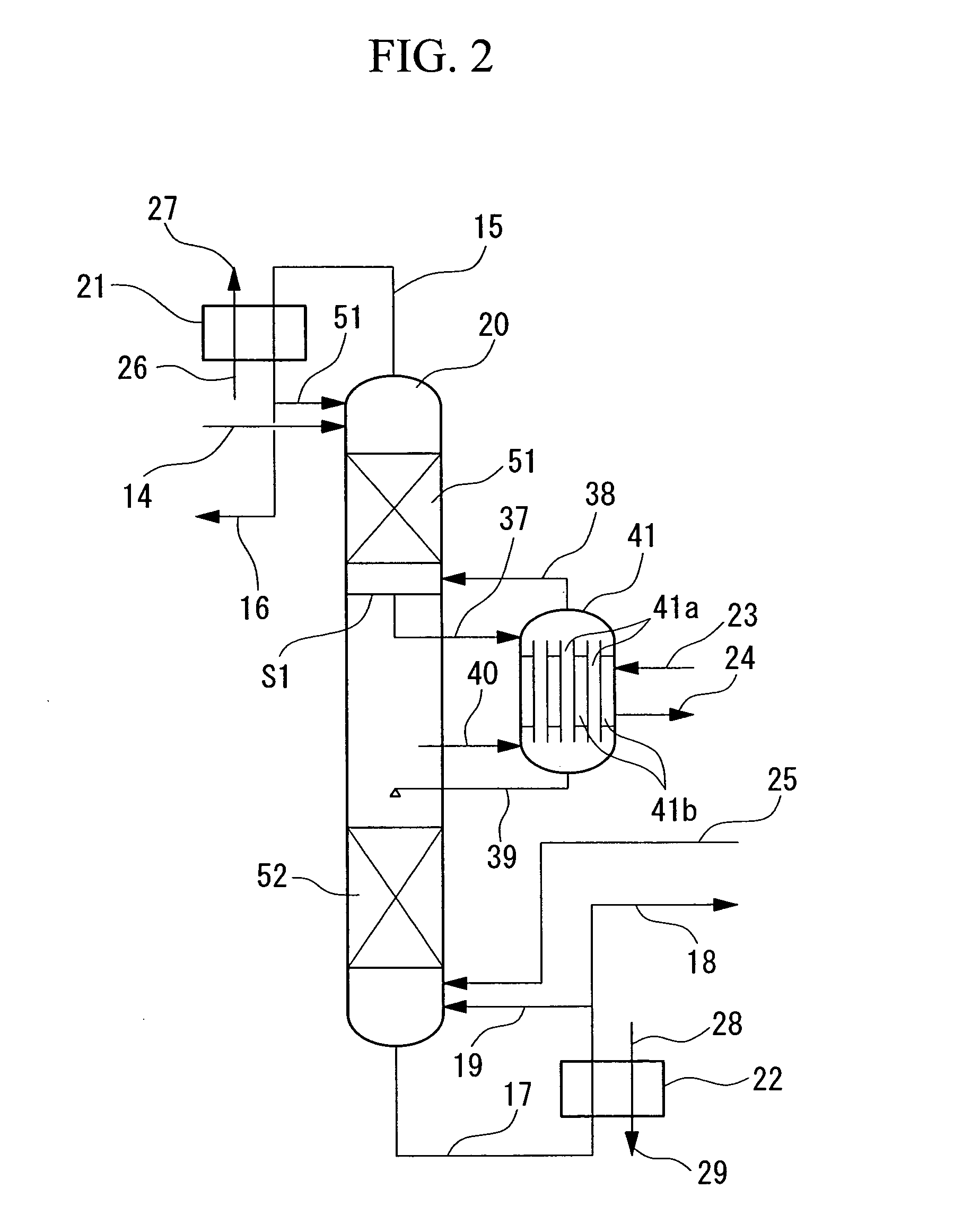
[0020] The present inventors solve the problem of increasing liquid holdup within the distillation apparatus inherent in conventional technology by applying a dephlegmator to the conventional separation and enrichment method in which mixtures with a separation factor close to 1 are separated and enriched by distillation, and they thereby achieve a shortening of the start-up time. The present invention provides a separation and enrichment method which can reduce the operational costs and can markedly improve productivity.

Problems solved by technology

Consequently, in this type of distillation apparatus, the start-up time (the time from the commencement of operations until a product is obtained) will be long.
However, no evidence has been provided as to whether or not the liquid holdup within a distillation apparatus can be reduced using these types of dephlegmators.
As described above, when a distillation method is used to separate and enrich a mixture with a separation factor close to 1, the problem of increased liquid holdup within the distillation apparatus arises.

Method used


Image

  • Method and device for separation and concentration by evaporation of mixture with separation factor of approx.1
  • Method and device for separation and concentration by evaporation of mixture with separation factor of approx.1
  • Method and device for separation and concentration by evaporation of mixture with separation factor of approx.1

Examples


Embodiment Construction

[0092] The data for each column is shown in Table 3, and the results of computer simulations are shown in Table 4 and Table 5.

[0093] Computer simulations based on the apparatus design shown in FIG. 7 for the present invention and the conventional technology, utilize a distillation theory using a rate model, or more specifically handle mass-transfer and heat-transfer simultaneously, and enable accurate prediction of mass-transfer in a multi-component-system within a dephlegmator when heat is applied or removed during distillation operation. Specific details relating to this simulation method are disclosed in Unexamined Japanese Patent Application, First Publication No. 2000-218134.

[0094] In the conventional models of H.E.T.P. (height equivalent to a theoretical plate) or equilibrium stage model, it has been not possible to predict accurately the mass-transfer in the above type of multi-component-system with simultaneous heat-transfer. Accordingly, such methods require experimental te...


PUM


Abstract

By using a dephlegmator which conducts distillation concurrently with heat exchange within at least one distillation column, or a portion of one distillation column, of a distillation cascade, the quantity of liquid holdup within the distillation apparatus is reduced and the start-up time is shortened. Consequently, the operational costs associated with startup are reduced, and productivity is improved markedly.

Description

[0001] The present invention relates to a method and apparatus for separating and enriching each of the components of a mixture with a separation factor close to 1, such as a mixture of structural isomers or isotopes, by low temperature distillation, and relates particularly to a method and apparatus for actively performing heat exchange concurrently with the distillation is integrated within either a portion of, or right through the entirety of, a cascade.[0002] This application is based on a patent application (No. 2000-356663) filed in Japan, the content of which is incorporated herein by reference.[0003] Methods for the separation and enrichment of mixtures of isotopes or structural isomers typically utilize distillation techniques. Mixtures of isotopes and structural isomers and the like often have separation factors close to 1. For example, the separation factor for xylene isomers (ratio of para / ortho vapor pressures) at a pressure close to atmospheric pressure is approximatel...

Claims


Application Information

Patent Timeline
Patent Type & Authority Applications(United States)
IPC IPC(8): B01D3/14B01D3/32B01D59/04F25J3/02F25J3/06F25J3/08
CPCB01D3/14B01D3/143B01D3/146B01D3/322B01D59/04Y10S203/11F25J2200/80F25J2210/50F25J2215/50Y10S423/07F25J3/08
Inventor ASANO, KOICHI.HAYASHIDA, SHIGERUEGOSHI, NOBUAKIKAWAKAMI, HIROSHI
Owner ASANO
Learn More