Oil-damped rolling bearing

a rolling bearing and oil-damping technology, applied in the direction of bearing unit rigid support, bearing cooling, liquid fuel engines, etc., can solve the problems of high pressure oil vibration-damping film, difficult to provide the shaft in question with a feed circuit that includes recovery scoops, feed ducts, and pumps, and achieve the effect of reducing the drawbacks

Active Publication Date: 2004-04-01
SN DETUDE & DE CONSTR DE MOTEURS DAVIATION S N E C M A
View PDF5 Cites 33 Cited by
  • Summary
  • Abstract
  • Description
  • Claims
  • Application Information

AI Technical Summary

Benefits of technology

The present invention is a new type of bearing for a turbomachine that can be lubricated and cooled. It also uses pressure to damp vibration and reduce the negative effects of previous designs.

Problems solved by technology

The technical problem addressed in this patent text needs to be identified by a senior R&D person who has read it through.

Method used


Image

  • Oil-damped rolling bearing
  • Oil-damped rolling bearing
  • Oil-damped rolling bearing

Examples


Embodiment Construction

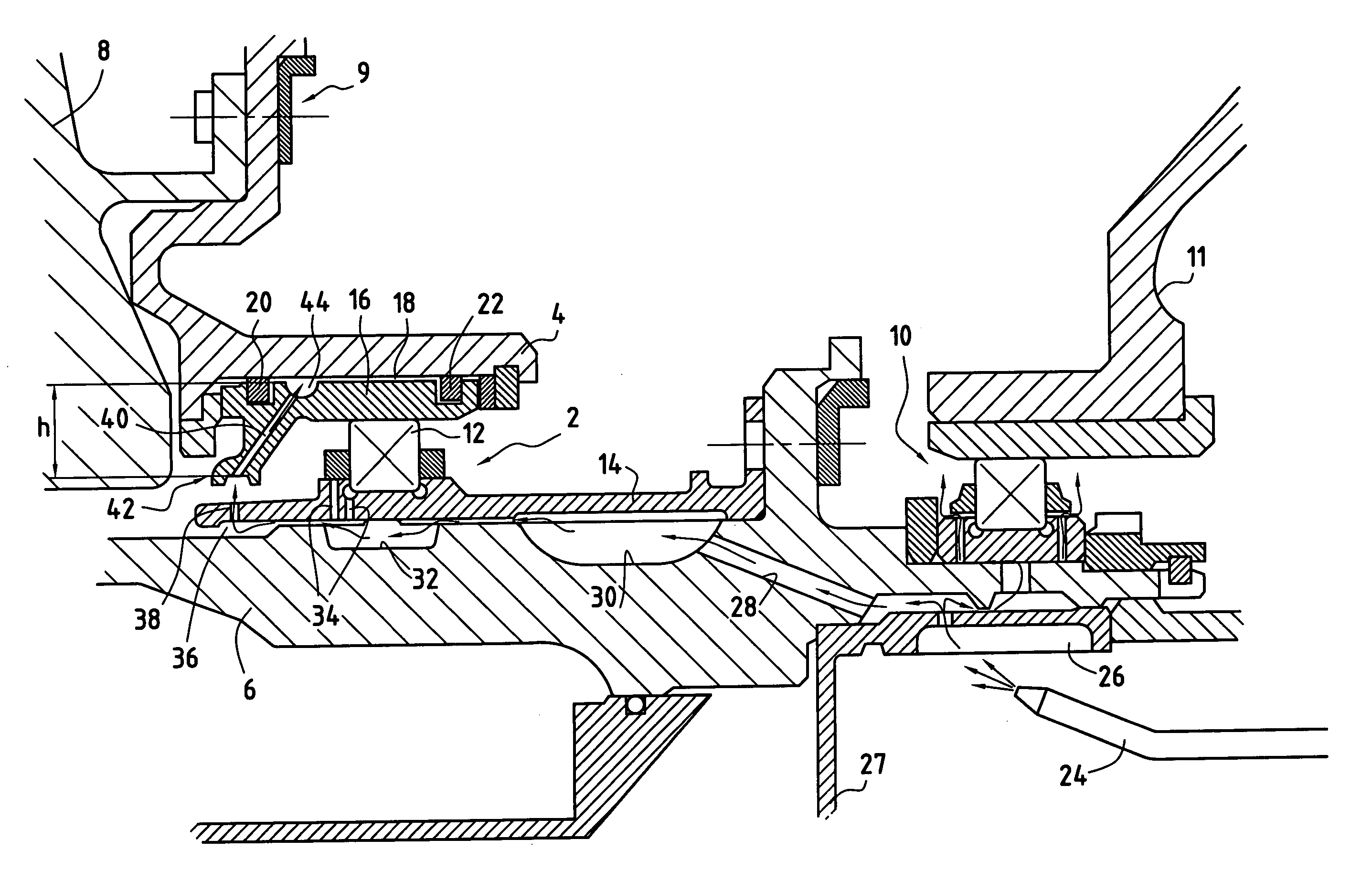
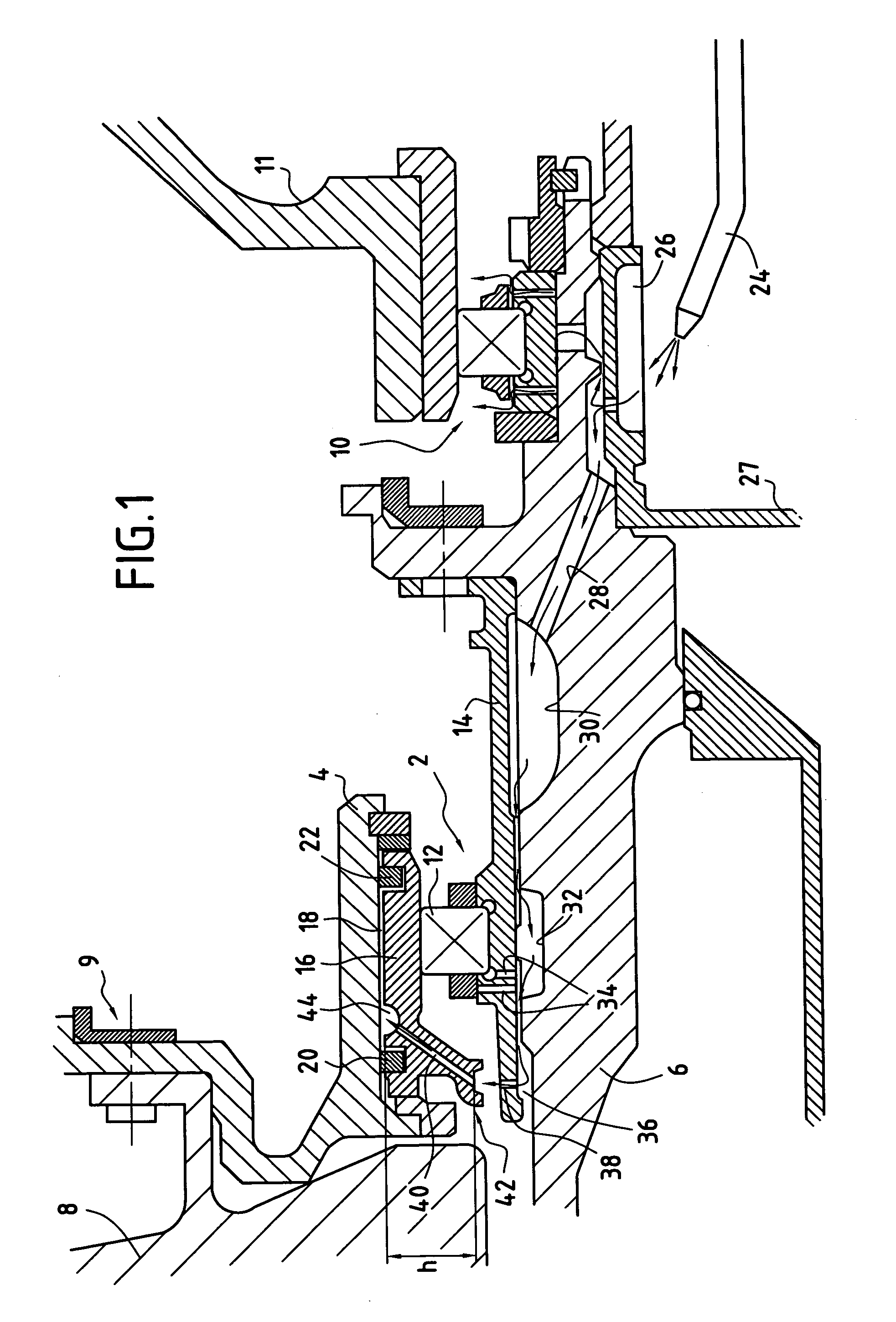
[0016] FIG. 1 shows a portion of a turbomachine in longitudinal section, said portion including a rolling bearing constituting a preferred embodiment of the invention.

[0017] The bearing 2 is disposed between a first shaft 4 which is the trunion of the shaft line of the high pressure spool of the turbomachine, and a second shaft 6 which is the trunion of the shaft line of the low pressure spool. The first shaft 4 is secured to the high pressure turbine 8 of the turbomachine via a fastening 9. Another rolling bearing 10 is also shown in FIG. 1. This bearing supports the second shaft 6 to rotate relative to a casing 11 of the turbomachine and does not form part of the present invention, so it is therefore not described in greater detail.

[0018] The bearing 2 is constituted by a plurality of rollers 12 engaged between the inside faces of an inner annular ring 14 and of an outer annular ring 16 forming races. The inner ring 14 is mounted on the second shaft 6. Similarly, the first shaft 4...


PUM


Abstract

A rolling bearing for a turbomachine supporting a first shaft to rotate relative to a second shaft, and comprising: a plurality of rolling elements engaged between an inner annular ring mounted on the second shaft and an outer annular ring mounted on the first shaft; an oil film formed at an annular contact surface between said outer ring and said first shaft; at least one duct passing through said inner ring and opening out in an inner race for said rolling elements in order to lubricate them; and at least one additional duct passing through said inner ring and opening out outside the inner race in order to feed oil through said outer ring to said oil film under the effect of the centrifugal force generated by said second shaft rotating, said outer ring having an annular shoulder projecting radially towards the inside of said annular space, said shoulder having at least one channel opening out substantially in register with said additional duct and opening out into said oil film.

Description


Claims


Application Information

Patent Timeline
Owner SN DETUDE & DE CONSTR DE MOTEURS DAVIATION S N E C M A
Why Eureka
Try Eureka