System and method for synchronizing multiple instrumentation devices

a technology of instrumentation device and synchronization method, which is applied in the field of instrumentation system, can solve the problems of not necessarily achieving the desired type of synchronization, not ensuring, and achieving digital synchronization may be even more difficul

Active Publication Date: 2004-04-01
NATIONAL INSTRUMENTS
View PDF8 Cites 69 Cited by
  • Summary
  • Abstract
  • Description
  • Claims
  • Application Information

AI Technical Summary

Problems solved by technology

Even though choosing the sample clock frequency to be an integer multiple of a common reference signal may result in sample clocks that are in phase from device to device (subject to various component and routing tolerances), it may not necessarily achieve a desired type of synchronization (e.g., digital synchronization).
In systems where the set of devices have sample clock frequencies that are not integer multiples of the sample clock frequency, achieving digital synchronization may be even more difficult.
However, rising edges on the reference clock may not correspond to rising edges on the sample c

Method used


Image

  • System and method for synchronizing multiple instrumentation devices
  • System and method for synchronizing multiple instrumentation devices
  • System and method for synchronizing multiple instrumentation devices

Examples


Embodiment Construction

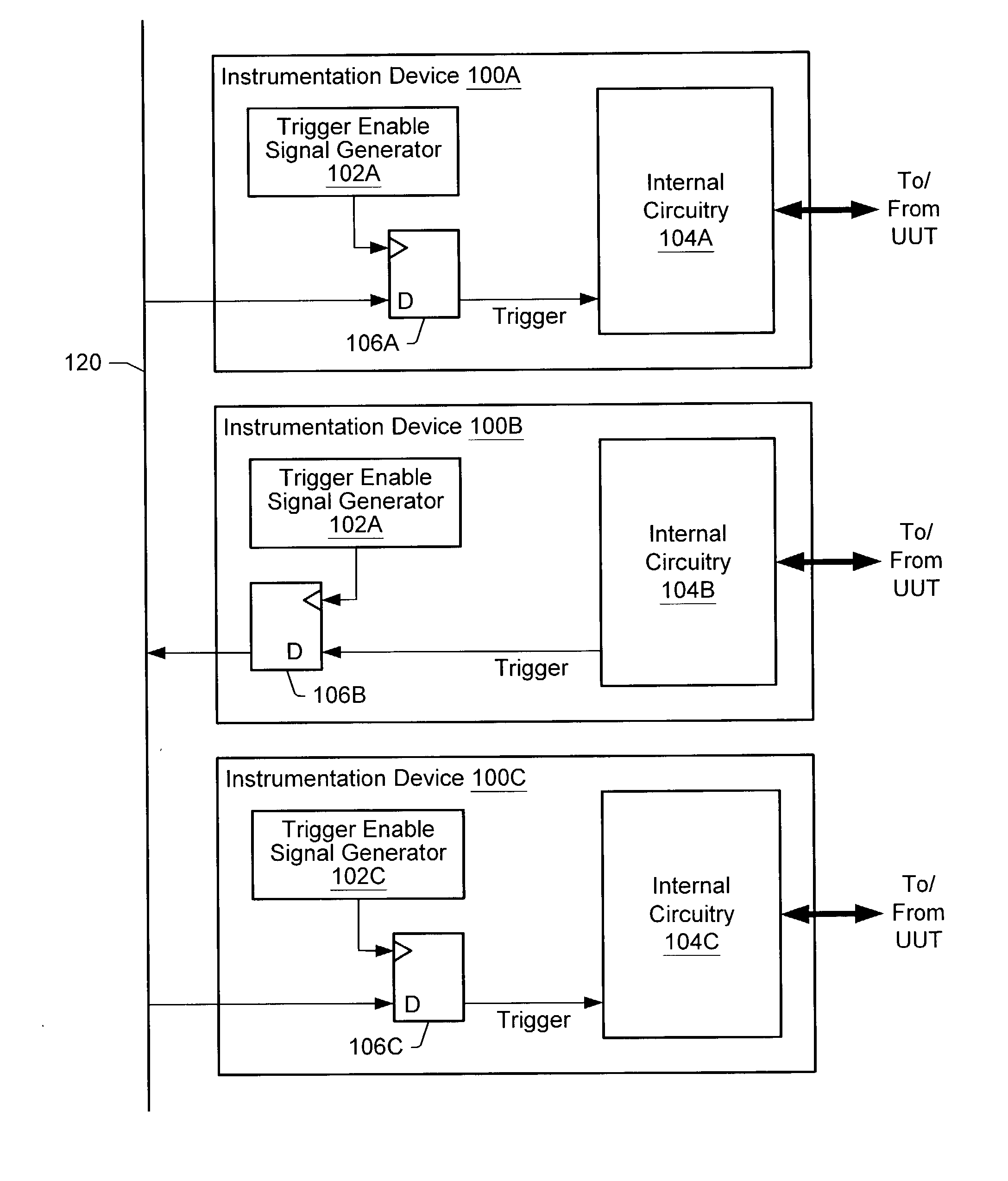
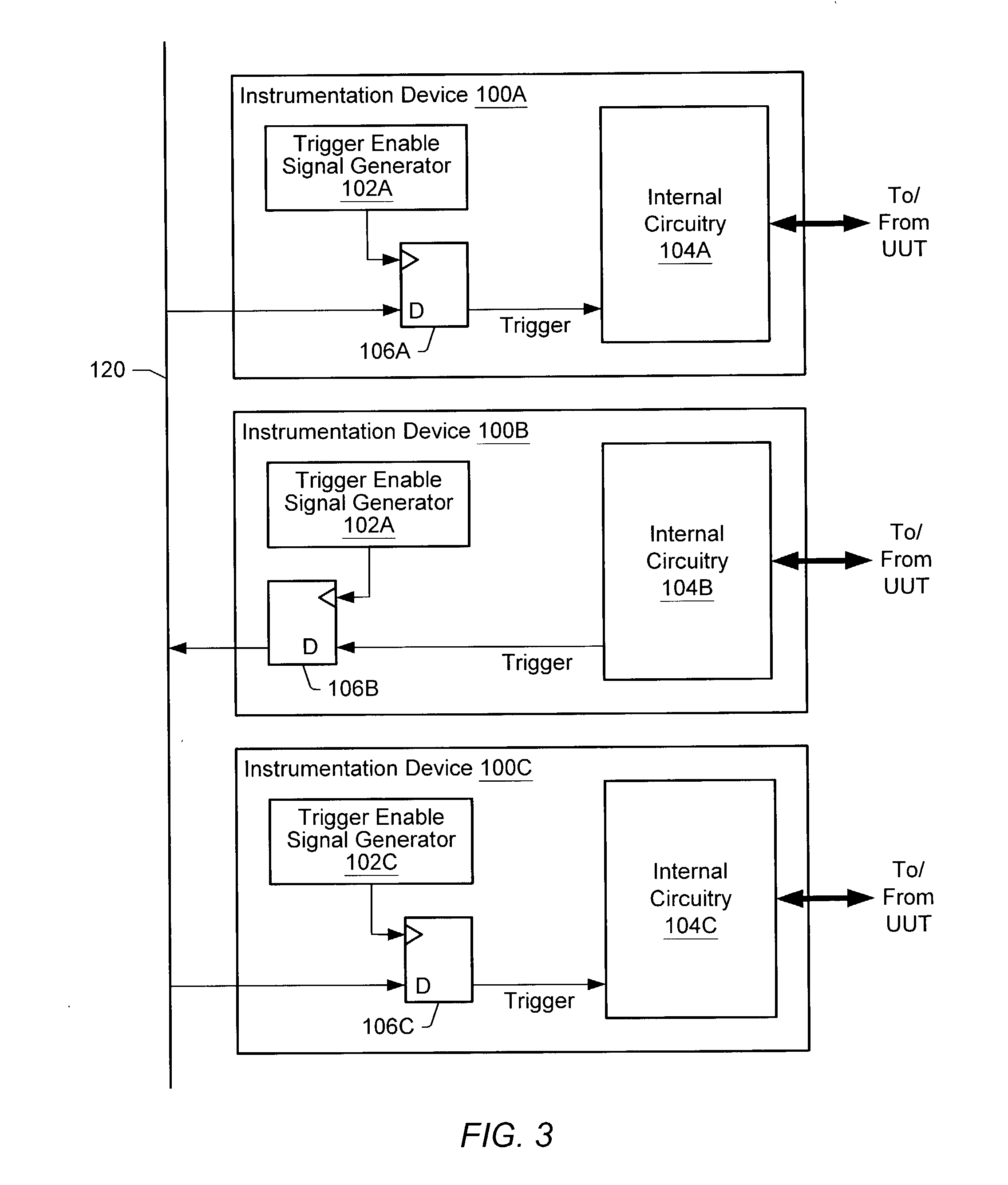
[0033] FIG. 3 shows a block diagram of one embodiment of an instrumentation system. Here, three instrumentation devices 100A, 100B, and 100C (collectively, instrumentation devices 100) are coupled by a communication medium 120. Each instrumentation device 100 may be configured to send and / or receive trigger signals on the communication medium 120. As shown, instrumentation device 100B may be configured to generate a trigger signal and to drive the trigger signal onto communication medium 120. Instrumentation devices 100A and 100C may be configured to receive the trigger signal from the communication medium 120. Each instrumentation device 100 includes respective internal circuitry 104A, 104B, 104C (collectively, internal circuitry 104) that may generate and / or receive trigger signals transmitted on communication medium 120. Each instrumentation device 100 may also be configured to provide stimuli to and / or receive stimuli from a unit under test (as shown), process under test, and / or...


PUM


Abstract

Trigger reception on different instrumentation devices may be synchronized by each instrumentation device generating one or more trigger enable signals and delaying performance of an operation in response to a trigger signal until a transition in a trigger enable signal. An instrumentation system may include several instrumentation devices and a communication medium coupling the instrumentation devices. One of the instrumentation devices may process data in response to a sample clock signal. That instrumentation device may also generate a trigger enable signal and delay performing an operation in response to a trigger signal transmitted via the communication medium until a transition in the trigger enable signal occurs. The trigger enable signal is not the sample clock signal. The trigger enable signal may be synchronized to another trigger enable signal generated by another one of the instrumentation devices.

Description

[0001] 1. Field of the Invention[0002] This invention relates to instrumentation systems and, more particularly, to synchronizing instrumentation devices.[0003] 2. Description of the Related Art[0004] Some instruments are devices that collect data or information from an environment or unit under test (UUT) and display this information to a user. An instrument may also analyze and process acquired data prior to displaying the data to the user. Some instruments provide test stimuli to a UUT. Examples of instruments include oscilloscopes, digital multimeters, pressure sensors, arbitrary waveform generators, digital waveform generators, etc. The information that may be collected by respective instruments includes information describing voltage, resistance, distance, velocity, pressure, frequency of oscillation, humidity, or temperature, among others.[0005] Computer-based instrumentation systems typically include transducers for transducing a physical phenomenon into an electrical signal...

Claims


Application Information

Patent Timeline
IPC IPC(8): G01R31/319G06F13/42
CPCG01R31/31907G01R19/2516
Inventor CONWAY, CRAIG M.
Owner NATIONAL INSTRUMENTS
Why Eureka
Try Eureka