

Susceptor device
a susceptor and base body technology, applied in the direction of ohmic resistance heating, hot plate heating arrangements, coatings, etc., can solve the problem that the adhesive layer 7 for attaching the susceptor base body 2 and the temperature control section 6 unitarily do not have a sufficient durability to corrosive gas or plasma
Active Publication Date: 2004-04-08
SUMITOMO OSAKA CEMENT CO LTD
View PDF5 Cites 43 Cited by
- Summary
- Abstract
- Description
- Claims
- Application Information
AI Technical Summary
Problems solved by technology
When an etching process is performed to the plate sample, for example, under a plasma atmospheric condition, there occurs a problem in that a temperature of a surface of the plate sample becomes high by a plasma heat; thus, a resist layer on the surface bursts.
However, in a conventional susceptor device 1 which is explained above, the adhesive layer 7 for attaching the susceptor base body 2 and the temperature controlling section 6 unitarily does not have a sufficient durability to a corrosive gas or a plasma.
Thus, there is a problem in that a thermal conductivity in the adhesive layer 7 is deteriorated; thus, it is difficult to control a temperature in the plate sample at a desirable constant temperature.
Also, there is a concern that the plate sample is contaminated and a particle is generated because a peripheral section of the adhesive layer 7 is exposed; thus a heavy metal which is contained in the adhesive layer 7 evaporates easily.
Therefore, there are concerns not only tha
Method used
View moreImage
Smart ImageViewing Examples

Examples
 PUM
| Property | Measurement | Unit |
|---|---|---|
| Pressure | aaaaa | aaaaa |
| Pressure | aaaaa | aaaaa |
| Pressure | aaaaa | aaaaa |
Abstract
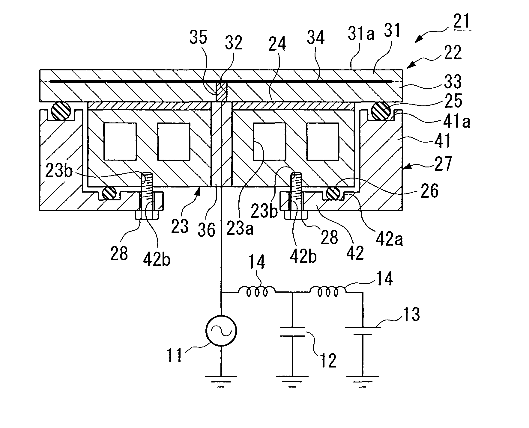
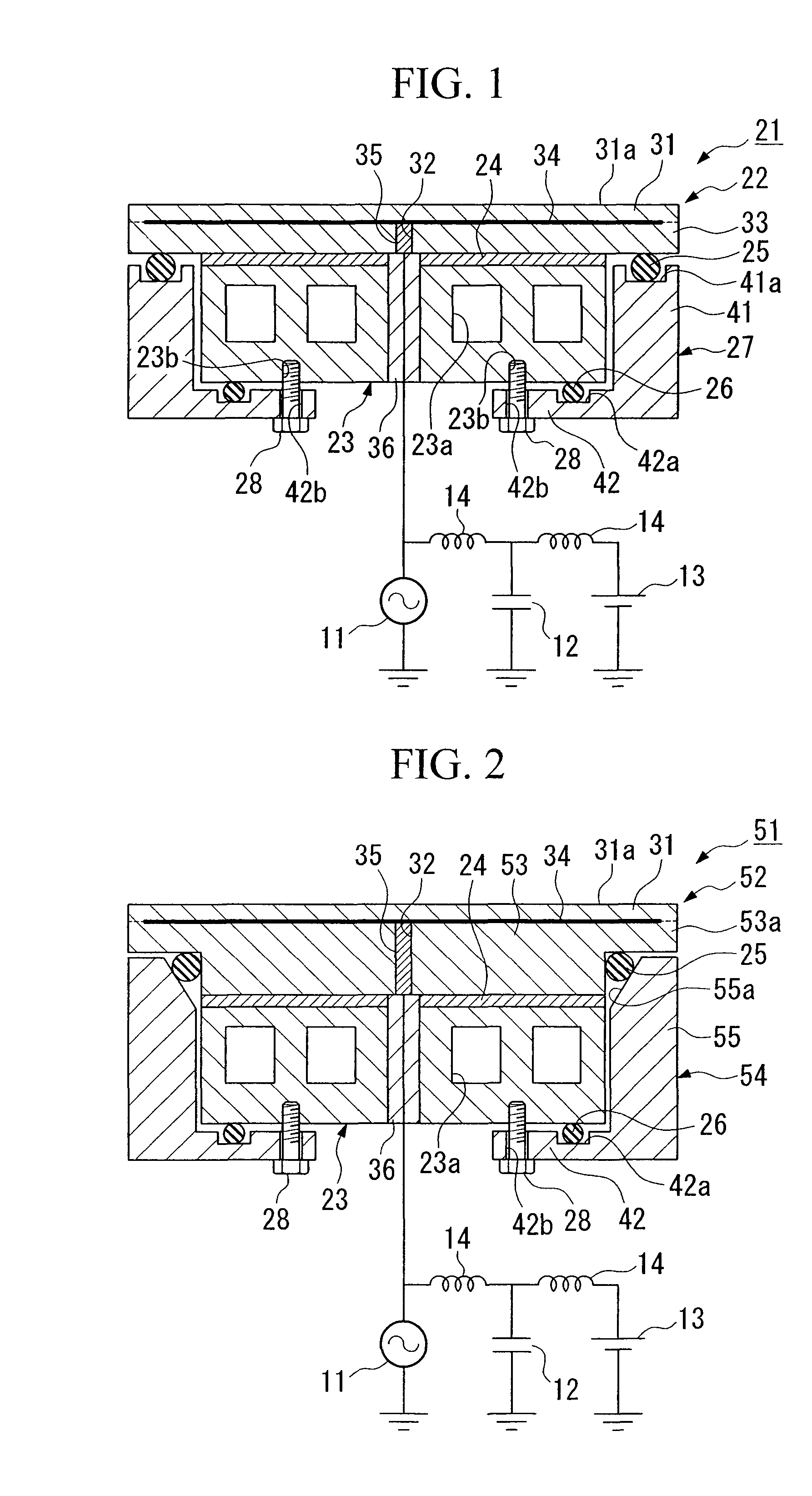
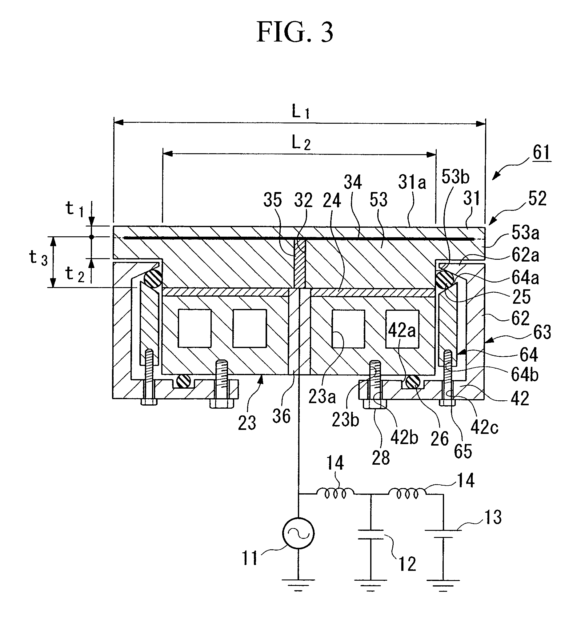
A susceptor device comprises a susceptor base body, a temperature controlling section, an adhesive layer which attaches the susceptor base body and the temperature controlling section unitarily, an O-ring which is disposed near a peripheral section of the adhesive layer, a circular O-ring which is disposed on a bottom surface of the temperature controlling section, an O-ring supporting section which surrounds the temperature controlling section and compresses the O-rings on the temperature controlling section, and pushup screws which push up and fix the O-ring supporting section toward the temperature controlling section. By doing this, it is possible to protect the adhesive layer from an external environment. Also, it is possible to provide a susceptor device having a superior temperature controlling characteristics for the plate sample, operational stability, and durability.
Description
[0001] 1. Field of the Invention[0002] Present invention relates to a susceptor device which is preferably used for fixing a plate sample such as a silicon wafer in a semiconductor manufacturing device for manufacturing a semiconductor device such as an IC (Integrated Circuit), LSI (Large Scale Integration), and a VLSI (Very Large Scale Integration). In particular, the present invention relates to a susceptor device which can maintain a temperature in a plate sample which is mounted on a mounting surface in the susceptor device at a predetermined temperature efficiently such that the susceptor device does not cause a contamination to the plate sample nor generates a particle with a superior durability.[0003] 2. Description of Related Art[0004] Conventionally, for example, a susceptor base body is used for a member for mounting the plate sample when various processes are performed to the plate sample such as a silicon wafer in processes for manufacturing a semiconductor device such a...
Claims
Login to View More Application Information
Patent Timeline
 IPC IPC(8): H01L21/00H01L21/687
CPCH01J37/32724H01J2237/2001H01L21/68785H01L21/67109H01L21/67103
InventorINAZUMACHI, HIROSHIKOSAKAI, MAMORU
OwnerSUMITOMO OSAKA CEMENT CO LTD