Snap connection for connecting two tube ends

a technology for connecting two tubes and ends, which is applied in the direction of hose connection, fluid pressure sealing joint, sleeve/socket joint, etc. it can solve the problems of relatively inflexible, relatively complicated structure, and unfavorable rubber hoses

Inactive Publication Date: 2004-04-15
EMS CHEM AG
View PDF5 Cites 18 Cited by
  • Summary
  • Abstract
  • Description
  • Claims
  • Application Information

AI Technical Summary

Problems solved by technology

Because of its high weight and high price, especially in large-volume air channels, rubber hoses are not very advantageous, however, and are already combined with lighter and cheaper plastic tubes, which, in turn, however, are relatively inflexible.
Overall, a relatively complicated structure with multiple sections of different materials and multiple connectors between the sections is provided.
This, in turn, requires a high manufacturing expense, a high expenditure for the logistics, as well as high assembly expenditure.
The multi-part structure also does not benefit the sealing capability of the line and forces a known minimal length, since the individual components can not be formed as short as desired.
Also, with the cramped proportions that are present today in most engine chambers of automobiles, sufficient space for the accessibility of the individual connectors must be provided.
Because of the lateral engagement of the stop spring, a relatively large amount of space must be provided for making and releasing the connection.

Method used


Image

  • Snap connection for connecting two tube ends
  • Snap connection for connecting two tube ends

Examples


Embodiment Construction

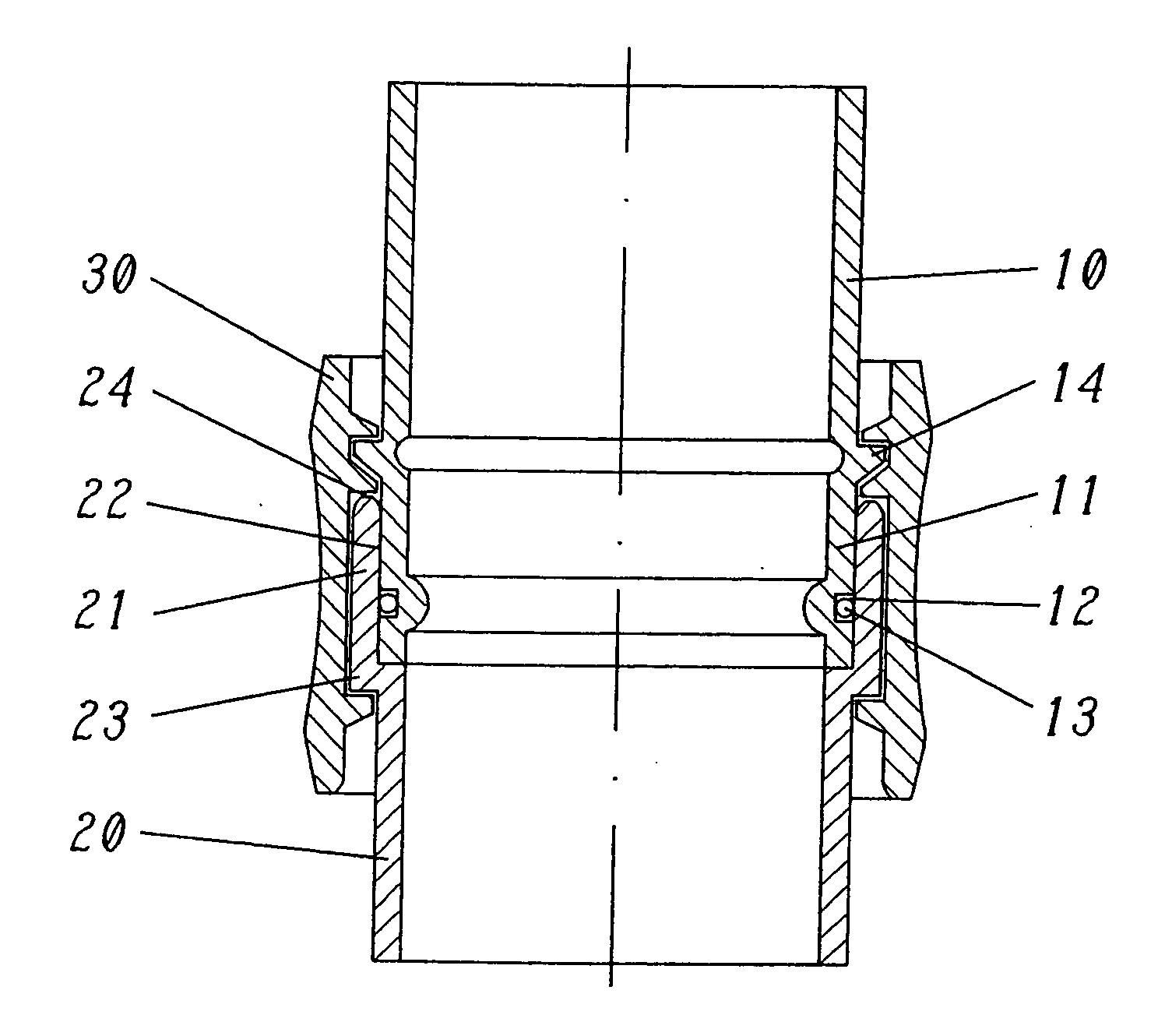
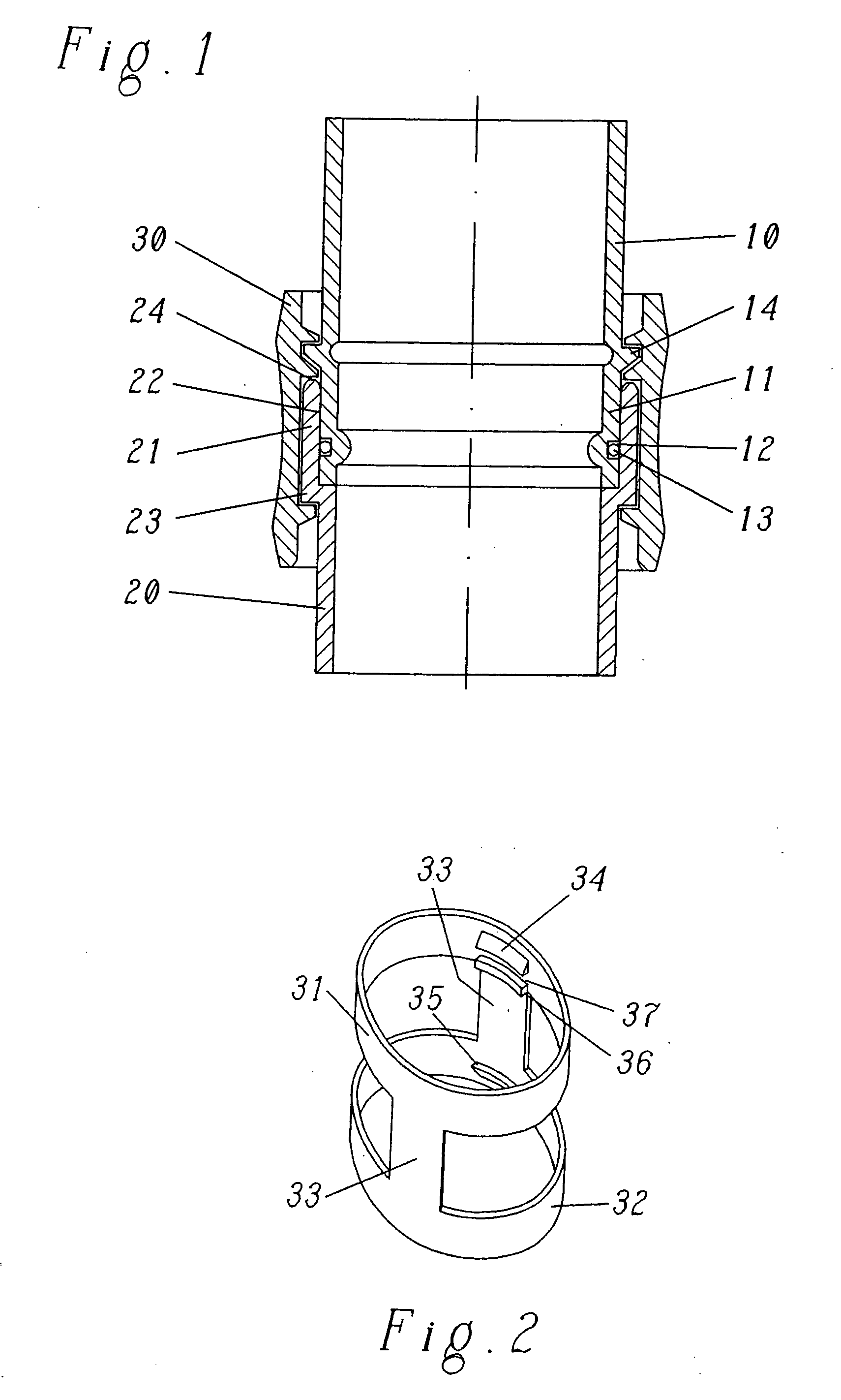
[0007] The invention is based on the object of providing a snap connection of the above-noted type, which assumes approved advantages of previously known solutions, can be made simply and rationally, is functionally broadened, and makes possible compact line connections.

[0008] The snap connection of the present invention, according to claim 1, is characterized by a second, outer stop projection on the second tube end, a second, elastically deformable ring connected with the spring arms with distance from the first ring, and by two, second inner stop cams on the second ring cooperating with the second outer stop projection.

[0009] With the snap connection of the present invention, in particular, the following advantages are achieved:

[0010] They enable manufacture by simple merging of the two tube ends with automatic snapping of the stop cams.

[0011] A sealed connection (in the practical sense) for use of fluids (fluids, steam or gas) is achieved.

[0012] For releasing the connection, the...


PUM


Abstract

The snap connection for sealed and releasable connection of a first tube end (10) with a second tube end (20), with spring arms (33), with a first outer stop projection (14) on the first tube end (10), with a first elastically deformable ring (31) connected with the spring arms (33), and with two first inner stop cams (34) on the first ring (31) cooperating with the first outer stop projection (14), is characterized according to the present invention by a second outer stop projection (23) on the second tube end (20), a second elastically deformable ring (32) connected with the spring arms (33) with distance from the first ring (31), and by two, second inner stop cams (35) on the second ring (32) cooperating with the second outer stop projection (23). Both rings with their stop cams, connected to one another via the spring arms, form a double-connection element (30) separable by and on both tube ends (10, 20), which can be made from a plastic injection molding part. The first tube end (10), for example, can be made by extrusion blow-molding and directly assembled with the second tube end (20), which can be a metal or plastic connecting piece, whereby the connection is fixed in a sealed position after the snapping of the double-connection element (30).

Description

[0001] The present invention relates to a snap connection for sealed and releasable connection of a first tube end with a second tube end, with spring arms, with a first outer stop projection on the first tube end, with a first elastically deformable ring connected with the spring arms, and with two first inner stop cams on the first ring cooperating with the first outer stop projection.STATE OF THE ART[0002] Snap connections of this type are also designated as "connectors". They are used, for example, in automobile construction, whereby they serve, among other things, for connection of fuel lines or air channels. With the term "channel", closed lines of any cross section are meant, in particular, however, tubes or pipes with a round cross section. Regularly, a connection to a metallic or also a non-metallic tube or a connecting piece is required. Because of the occurring vibrations, it is necessary to form at least a part of the line or channel to be elastically resilient. For this...

Claims


Application Information

Patent Timeline
Patent Type & Authority Applications(United States)
IPC IPC(8): F16L37/08F16L37/084
CPCY10S285/921F16L37/084F16L37/0985F16L37/08
Inventor THOMAS, JELTSCHKETTL, RALPHMARIO, WILLI
Owner EMS CHEM AG
Why Eureka
Try Eureka