Supercharge Your Innovation With Domain-Expert AI Agents!

Optical pickup apparatus

Inactive Publication Date: 2004-04-15
PIONEER CORP
View PDF3 Cites 5 Cited by
  • Summary
  • Abstract
  • Description
  • Claims
  • Application Information

AI Technical Summary

Problems solved by technology

When an optical pickup apparatus is constructed using the above described semiconductor laser unit with two wavelengths, the positional relationship between the central axis (optical axis) of the optical system extending from the light source to the disc and the light source is an important issue.
However, since the above described semiconductor laser unit with two wavelengths has two light sources for CD and DVD, it is physically impossible to place both lights sources on the optical axis.
However, if the DVD light source is placed in a position shifted from the optical axis, the laser beam emitted from the DVD light source has a height of an image relative to the objective lens, thus causing coma aberration.
Furthermore, the amount of coma aberration generated also varies depending on the design of the objective lens used, and therefore depending on the size of the objective lens used, coma aberration associated with the shape and position of the objective lens occurs in addition to coma aberration caused by an image height of the laser beam for DVD.
As a result, the total amount of coma aberration grows considerably and deteriorates the optical characteristic of the optical pickup apparatus.
(a) Coma aberration on the objective lens, which is associated with the angle of incidence on the collimator lens due to the image height on the CD light source side;
(b) Coma aberration on the objective lens, which is associated with the angle of incidence on the collimator lens due to the image height on the DVD light source side;
(c) Coma aberration associated with the tilting amount of the objective lens on the CD light source side, and
(d) Coma aberration associated with the tilting amount of the objective lens on the DVD light source side.

Method used


Image

  • Optical pickup apparatus
  • Optical pickup apparatus
  • Optical pickup apparatus

Examples


Embodiment Construction

[0028] Now, preferred examples of the present invention will be described below with reference to the accompanying drawings.

Optical Pickup Apparatus

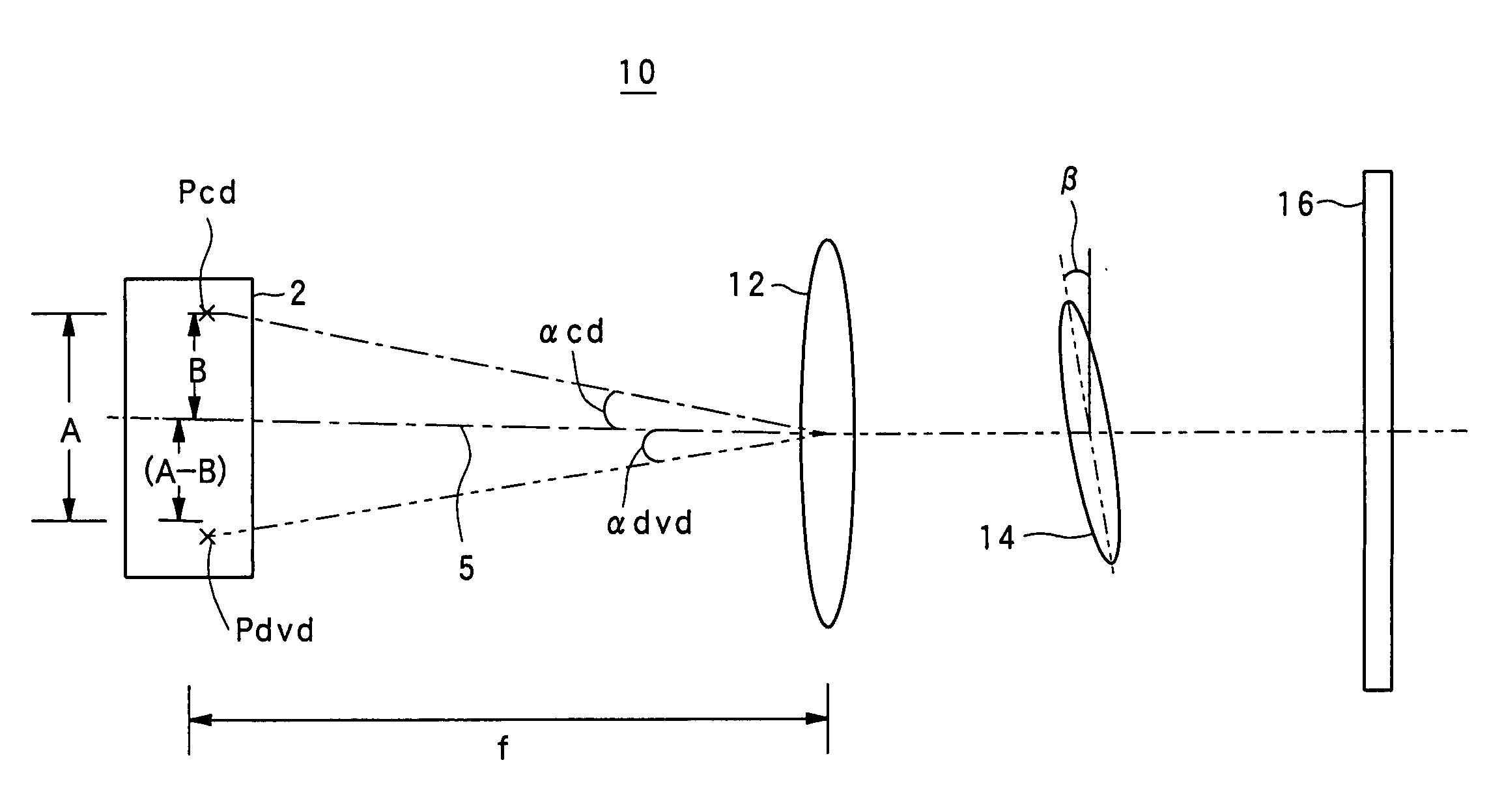
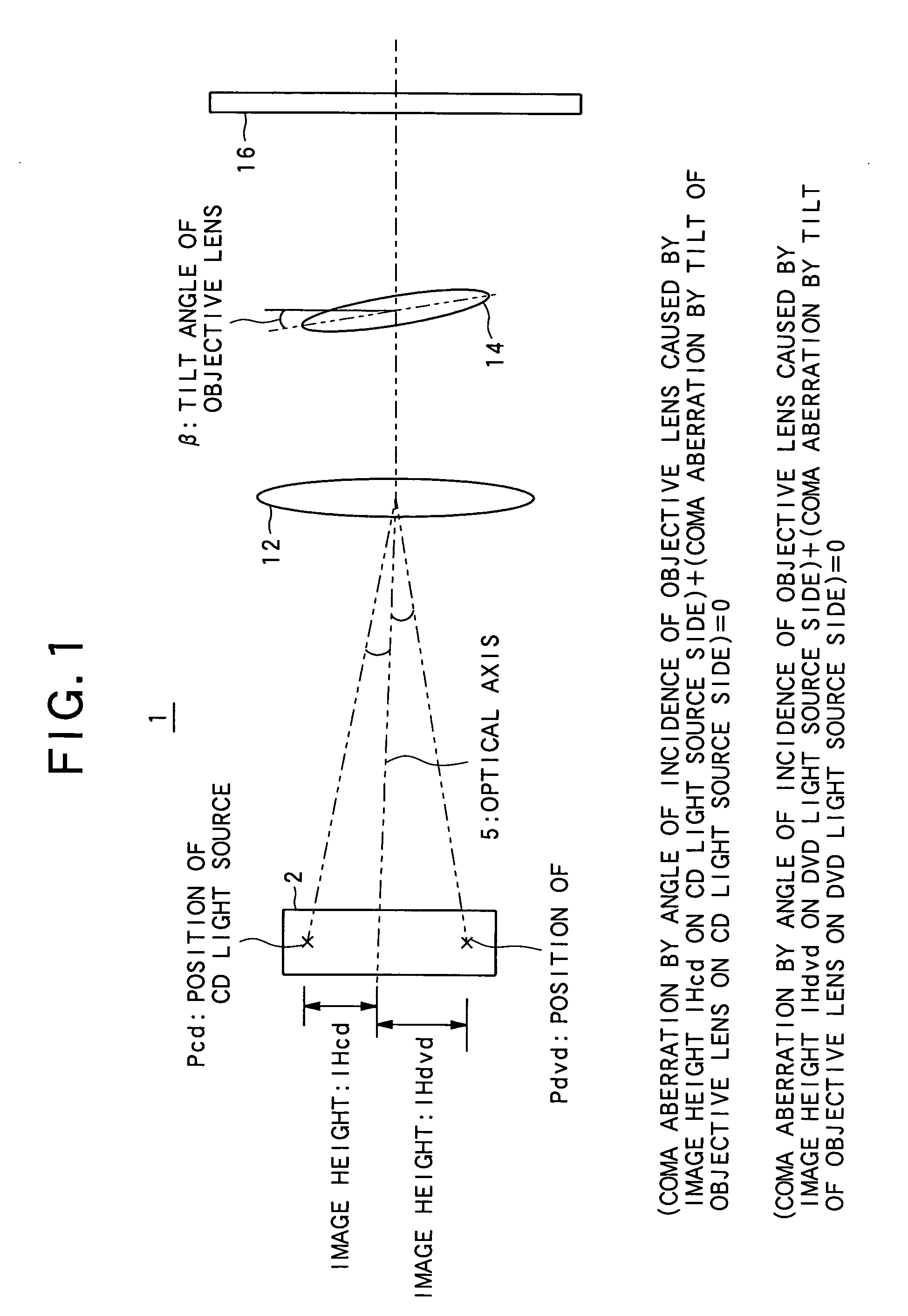
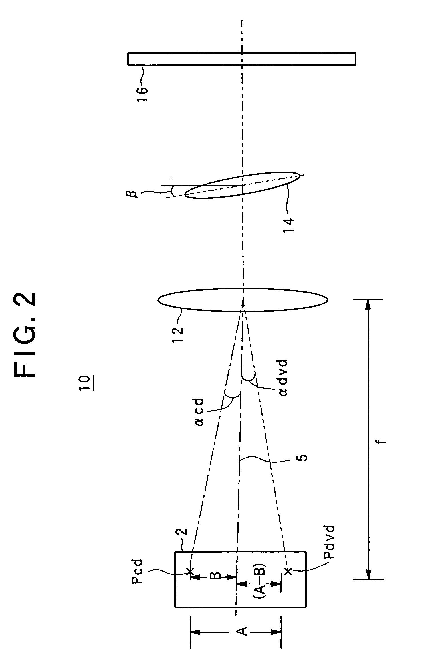
[0029] FIG. 2 shows a positional relationship of the optical system of the optical pickup apparatus according to an example of the present invention. As shown in FIG. 2, an optical pickup 10 includes a double-wavelength semiconductor laser unit 2. The position of the CD light source is indicated as "Pcd" and the position of the DVD light source is indicated as "Pdvd." Furthermore, a collimator lens 12 and an objective lens 14 are placed on an optical axis 5. The laser beams emitted from the CD light source and the DVD light source are transformed into parallel beams through the collimator lens 12 and condensed onto an information recording surface of a disc 16 by the objective lens 14.

[0030] The position "Pcd" of the CD light source and the position "Pdvd" of the DVD light source are kept away from each other by a predetermined distance ...


PUM


Abstract

An optical pickup apparatus comprises a first light source for emitting a first laser beam having a first wavelength; a second light source for emitting a second laser beam having a second wavelength; and an objective lens for condensing the first laser beam and the second laser beam. The first light source and the second light source are disposed in positions in such a way that a total amount of coma aberration, which is generated on the first laser beam in accordance with a distance between the first light source and an optical axis of a whole optical system and coma aberration, which is generated on the first laser beam in accordance with a tilting amount of the objective lens becomes null, and a total amount of coma aberration, which is generated on the second laser beam in accordance with a distance between the second light source and said optical axis and coma aberration, which is generated on the second laser beam in accordance with the tilting amount of the objective lens becomes null.

Description

[0001] 1. Field of the Invention[0002] The present invention relates to an optical pickup apparatus.[0003] 2. Description of the Related Art[0004] As a light source of an optical pickup apparatus that reproduces an optical information recording medium such as a CD (Compact Disc) and DVD (Digital Versatile Disc), a semiconductor laser element is generally used. The wavelength of a laser beam as used and the number of apertures (NA) of the objective lens as used differ depending on whether a recording medium to be reproduced is a CD or DVD. For example, the wavelength of the laser beam is 650 nm and NA is 0.6 for a DVD. On the other hand, the wavelength of the laser beam is 780 nm and NA is 0.45 for a CD.[0005] In order to allow a single player to reproduce both CD and DVD, an optical pickup apparatus incorporating a light source with two wavelengths of 650 nm and 780 nm has been under development and a semiconductor laser unit for emitting laser beams having two different wavelengths...

Claims


Application Information

Patent Timeline
IPC IPC(8): G02B27/00G11B7/00G11B7/125G11B7/135G11B7/1374G11B7/1376G11B7/1378G11B7/1392G11B7/22
CPCG02B27/0025G11B7/0956G11B7/135G11B7/1374G11B2007/0006G11B7/1378G11B7/13922G11B7/22G11B7/1376
Inventor FURUHATA, HITOSHIKOYAMA, MASAYUKINISHIMURA, TOMOTAKA
Owner PIONEER CORP
Features
  • R&D
  • Intellectual Property
  • Life Sciences
  • Materials
  • Tech Scout
  • Unparalleled Data Quality
  • Higher Quality Content
  • 60% Fewer Hallucinations
Learn More