Spring support having a height-adjustable spring plate

a spring plate and height adjustment technology, applied in the field of spring plates, can solve the problems of laborious task of torsional safeguarding of spring plates, difficult production of torsional safeguards, such as creases in domes,

Inactive Publication Date: 2004-04-22
ZF SACHS AG
View PDF14 Cites 71 Cited by
  • Summary
  • Abstract
  • Description
  • Claims
  • Application Information

AI Technical Summary

Problems solved by technology

It is to be feared that in addition to the forced vibration emanating from the sprung wheel, a second vibration also acts on the vehicle spring, namely that resulting from the torque bracing of the spring plate in opposition to the drive torque of the electric motor.
On closer examination, however, it will be noted that p

Method used


Image

  • Spring support having a height-adjustable spring plate
  • Spring support having a height-adjustable spring plate
  • Spring support having a height-adjustable spring plate

Examples


Embodiment Construction

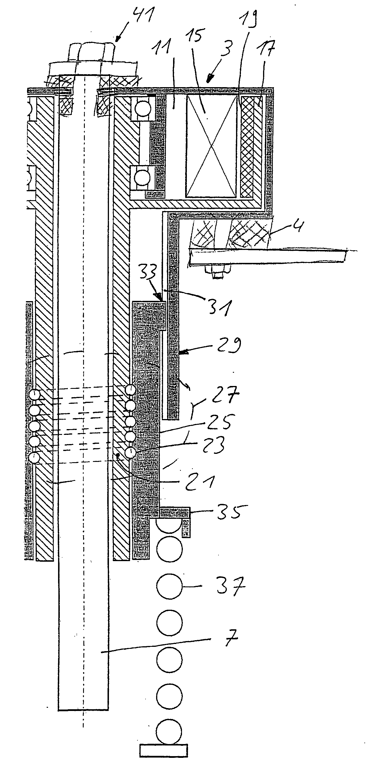
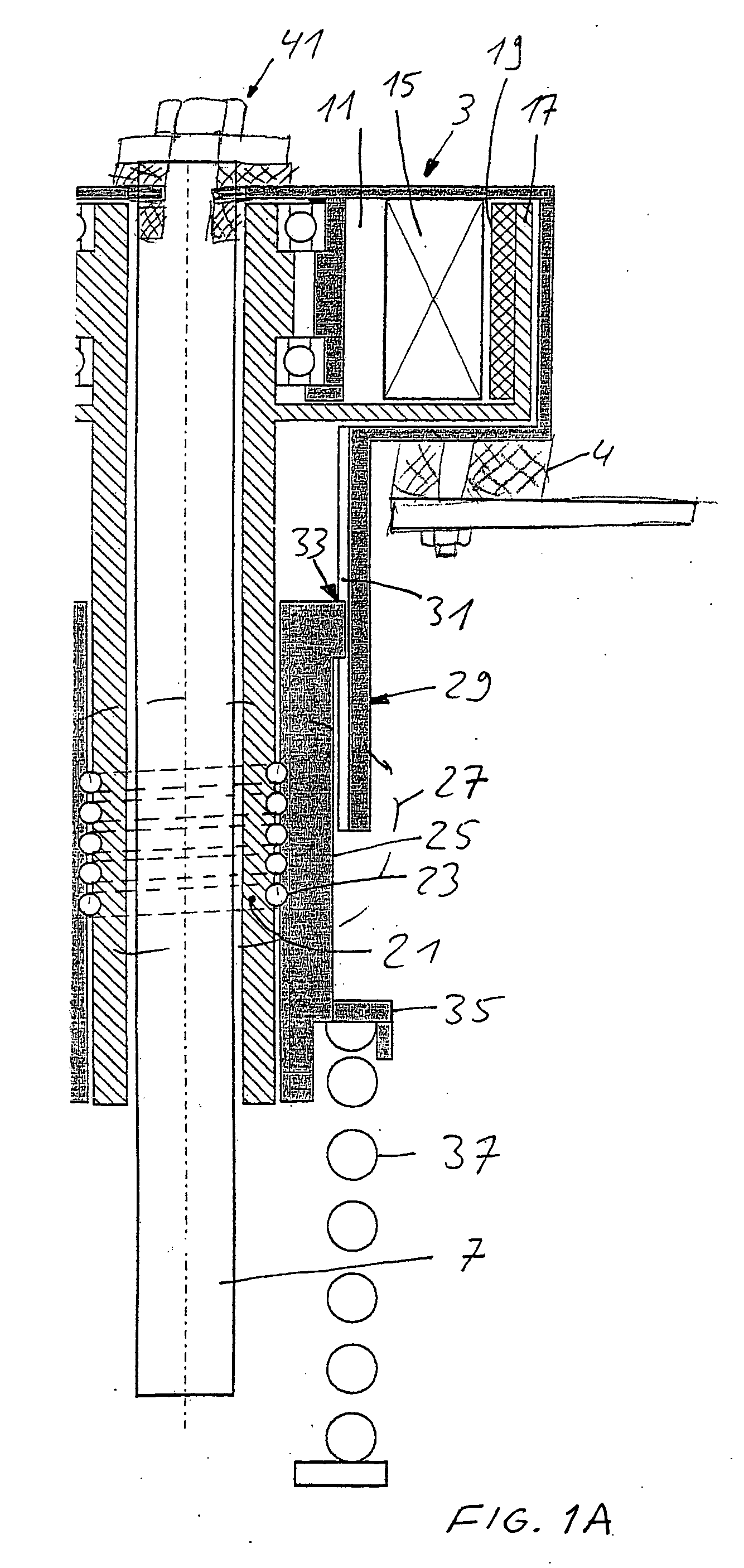
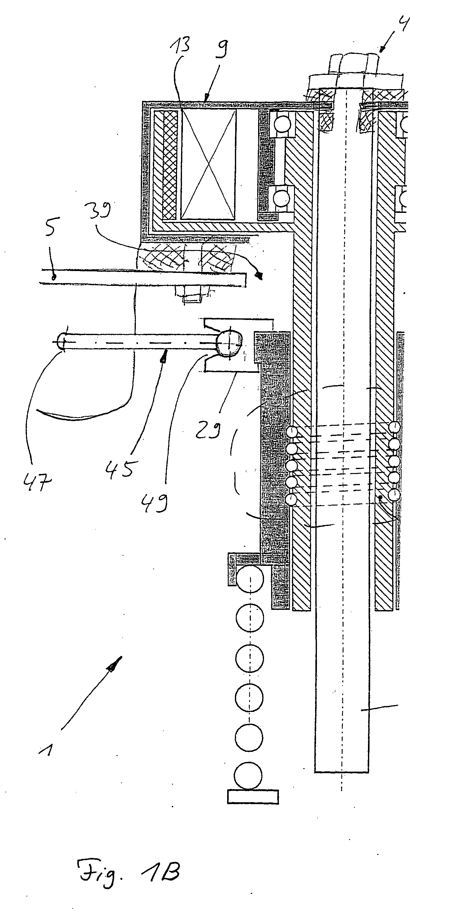
[0025] FIG. 1A is confined to the upper part of a spring support 1 having an actuator 3 on a vehicle body 5. The spring support may be a vibration damper, for example, of which the rod 7 is represented.

[0026] The actuator 3 is arranged inside a housing 9 and has a stator 11 fixed to the housing, with torque generating surfaces 13 comprising a number of coils 15, and a rotor 17, arranged radially outside this and having torque generating surfaces 19 in the form, for example, of permanent magnets. Theoretically, the design of the actuator may differ from this principle with regard to the technical design of the torque generating surfaces.

[0027] The rotor 17 is supported inside on the stator and extends concentrically around the rod 7. Arranged on the outside thereof is a force introducing profile 21, which together with a mating profile 23 on an inner side of a force transmitting element 25 forms a movement converting device in the form of a spindle 27. Rolling elements may be used be...


PUM


Abstract

Spring support having at least one axially moveable spring plate, an actuator with a rotor producing a rotational movement relative to its stator, which is converted into an axial movement of the spring plate, and a torsional locking element which prevents torsional movement of the spring plate.

Description

[0001] 1. Field of the Invention[0002] The invention relates to a spring support having an axially movable spring plate, an actuator including a rotor and a stator, force-transmitting element which moves axially in response to rotation of the rotor, and a spring plate fixed to the force transmitting element.[0003] 2. Description of the Related Art[0004] WO 02 / 055326 describes a vehicle suspension in which a vibration damper has an axially adjustable spring plate. An electric motor having an external stator and an internal rotor, the rotational movement of which is translated into an axial movement by a movement converting device in the form of a threaded spindle, serves as actuator. The inner side of the rotor and an outer side of a sleeve-shaped extension of the axially moveable spring plate form the threaded spindle.[0005] In order to fulfill the function of a threaded spindle it is necessary that the spring plate be incapable of performing a rotational movement. Two possible ways...

Claims


Application Information

Patent Timeline
IPC IPC(8): B60G11/16B60G17/02F16F1/12
CPCB60G11/16B60G17/021B60G2202/42B60G2500/20Y10T74/1868F16F1/12F16F1/127Y10T74/18576B60G2500/30
Inventor KUHNEL, JOACHIM
Owner ZF SACHS AG
Why Eureka
Try Eureka