Optical amplification structure with an integrated optical system and amplification housing integrating one such structure

a technology of optical amplification and integrated optical system, which is applied in the direction of lasers, fiber transmission, transmission, etc., can solve the problems of deteriorating the components or systems receiving light wave leaving the amplifying structure, and affecting the performance of the amplifier, so as to prevent reflection

Inactive Publication Date: 2004-04-22
TEEM PHOTONICS
View PDF7 Cites 8 Cited by
  • Summary
  • Abstract
  • Description
  • Claims
  • Application Information

AI Technical Summary

Benefits of technology

0055] The connecting means of the second fibre furthermore comprise an optical insulator c

Problems solved by technology

However, the output of these amplifying structures does not deliver solely the amplified light wave S. In fact, at the output of the micro-waveguide 6, the resulting light wave always includes a residual compo

Method used


Image

  • Optical amplification structure with an integrated optical system and amplification housing integrating one such structure
  • Optical amplification structure with an integrated optical system and amplification housing integrating one such structure
  • Optical amplification structure with an integrated optical system and amplification housing integrating one such structure

Examples


Embodiment Construction

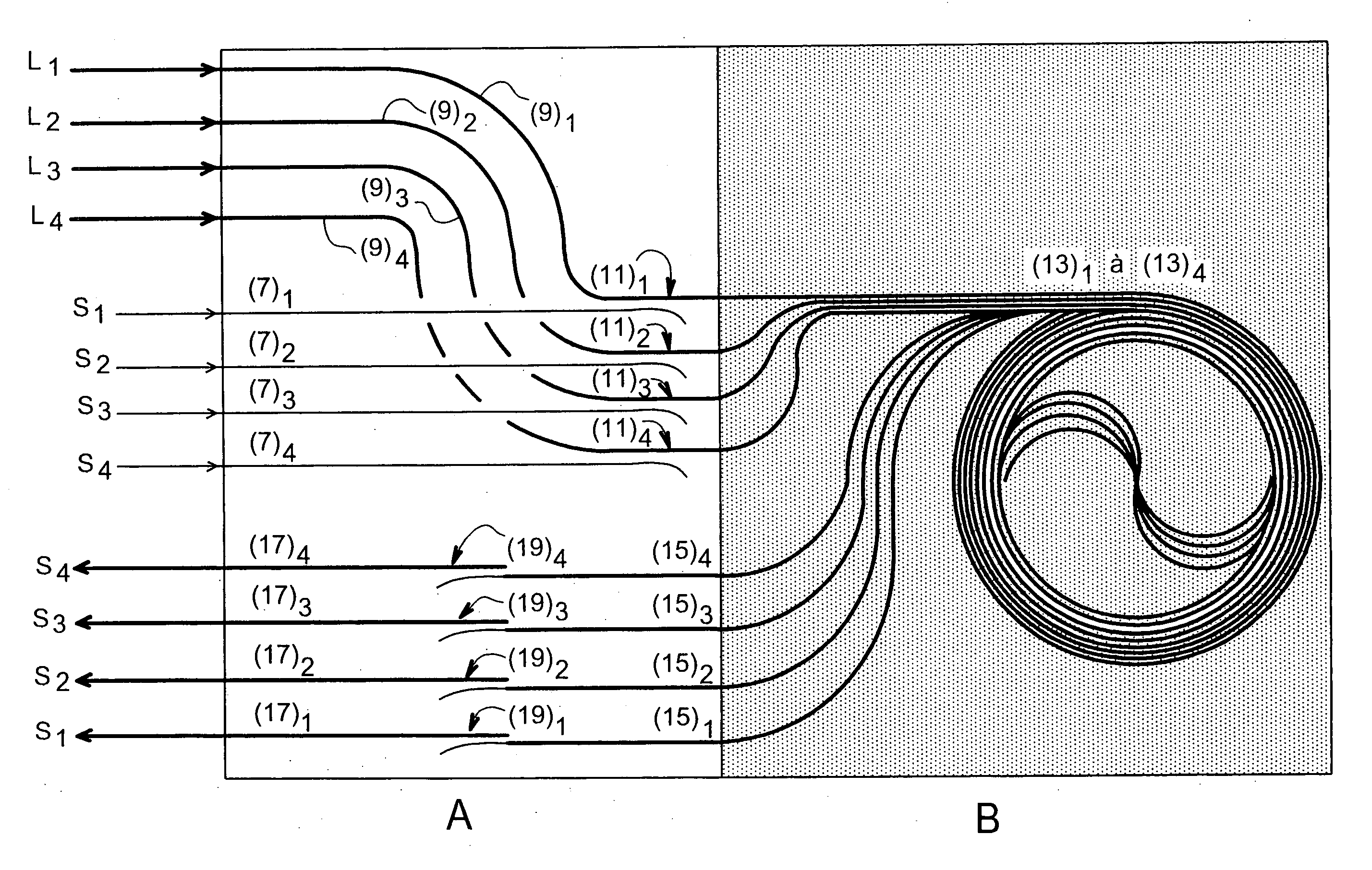
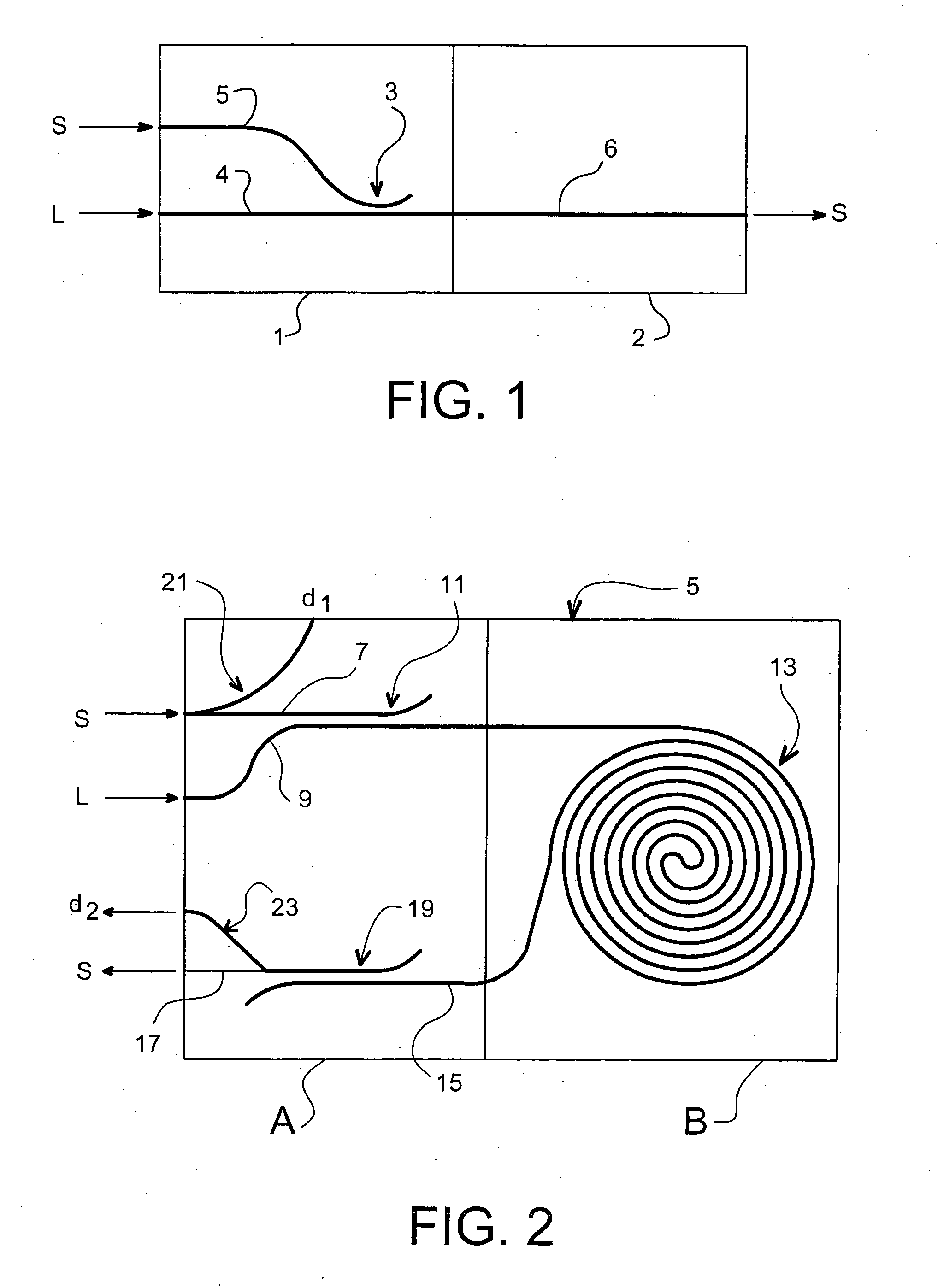
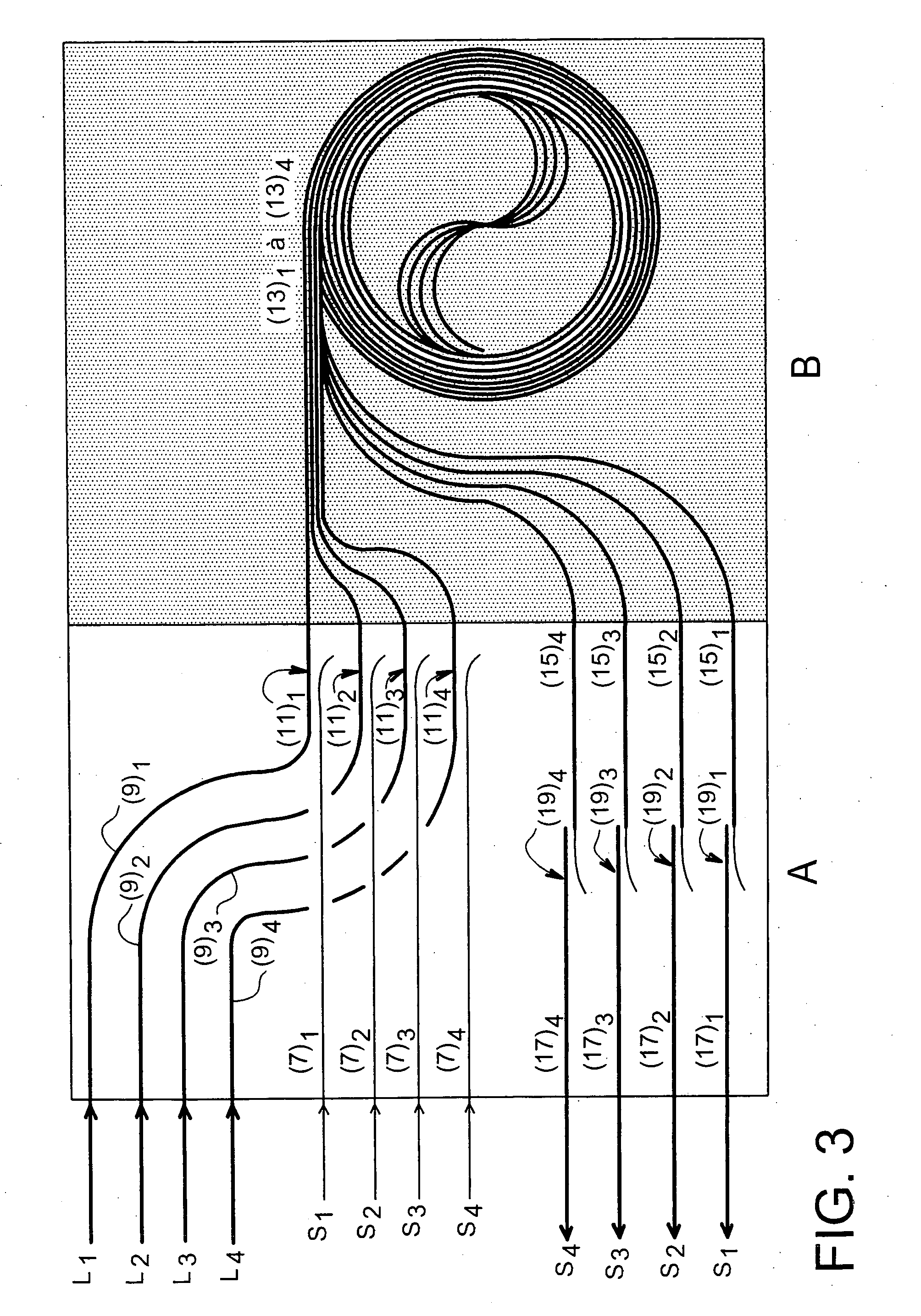
[0061] FIG. 2 shows schematically an amplifying structure according to the invention, for a light wave S to be amplified. In this diagram is shown a section of the substrate in which the structure is implemented, along a plane containing the different directions of propagation of light waves in the micro-waveguides, it being understood that according to the technologies used, these directions are of course not in practice necessarily contained in only one plane.

[0062] The amplifying structure shown in this figure permits one light wave S to be amplified and thus comprises a single amplifying assembly in a substrate 5. This assembly is composed of:

[0063] a first micro-waveguide 7 capable of receiving the light wave S to be amplified,

[0064] a second micro-waveguide 9 capable of receiving a pumping wave L,

[0065] a multiplexing device 11 associated with the first and second micro-waveguides, and capable of providing a light wave composed of the wave S and the wave L,

[0066] an amplifying...


PUM


Abstract

The invention relates to an optical amplifying structure capable of amplifying at least one light wave S, comprising in a substrate, for each wave to be amplified, an amplifying assembly composed of: a first micro-waveguide (7) capable of receiving the light wave S to be amplified, a second micro-waveguide (9) capable of receiving a pumping wave L, a multiplexing device (11) associated with the first and second micro-waveguides, and capable of providing a coupled light wave composed of the wave S and the wave L, an amplifying device (13) connected to an output of the multiplexing device and capable of amplifying the light wave S by at least partial absorption of the pumping wave L, the amplifying device being capable of providing at one output the amplified light wave S. a third micro-waveguide (15) connected to the output of the amplifying device and capable of carrying the amplified light wave S, and a demultiplexing device (19) associated with the third micro-waveguide and capable of demultiplexing the pumping wave L from the amplified wave S, and of providing on a fourth micro-waveguide (17) an amplified light wave S, purged of the pumping wave. The structure of the invention is applied to all fields necessitating an amplification of a light wave and in particular in the field of optical telecommunications by optical fibres.

Description

[0001] The present invention relates to an optical amplifying structure implemented in integrated optics, and an amplifying package integrating such a structure.[0002] It is applicable in all fields requiring the amplification of a light wave and in particular in the field of optical telecommunications by optical fibres.STATE OF THE ART[0003] FIG. 1 is a diagram showing the principle of a conventional amplification structure implemented in integrated optics.[0004] To amplify a light wave, the optical amplifying structures at present implemented in integrated optics comprise two portions in which optical waveguides are formed.[0005] An optical waveguide is composed of a central portion, generally termed core, and surrounding media situated all around the core and which may be the same as each other or different.[0006] To permit confinement of the light in the core, the refractive index of the core medium should be different from, and in most cases greater than, those of the surroundi...

Claims


Application Information

Patent Timeline
IPC IPC(8): G02B6/122H01S3/06H01S3/063H01S3/067H01S3/10
CPCH01S3/0632H01S3/0637H01S3/06754H01S3/06708H01S3/06704
Inventor PHILIPSEN, JACOBBARBIER, DENISCASSAGNETTES, CEDRICVALETTE, SERGE
Owner TEEM PHOTONICS
Why Eureka
Try Eureka