Slide fastener

a slider and fastener technology, applied in the field of sliders, can solve the problems of sliders partially clogging the upper stopper, user cannot help feeling a heaviness, and the fastener tape is too thick

Active Publication Date: 2004-04-29
YKK CORP
View PDF4 Cites 3 Cited by
  • Summary
  • Abstract
  • Description
  • Claims
  • Application Information

AI Technical Summary

Problems solved by technology

However, because the upper stopper portions of these known slide fasteners are molded on only the top face of the fastener tape by welding, their mounting strength on the fastener tape is weak and the stopper portion which receives the largest impact when a slider flange strikes it is separated easily from the fastener tape, so that they do not endure a long-term usage.
Thus, a contact area with an inner face of a slider is large and at the time of starting sliding of the slider so as to open the slide fastener, its sliding resistance is large so that a user cannot help feeling a heaviness.
Because when the upper stopper makes a contact with the slider, a quite large striking force is applied to the upper stopper due to the sliding operation of the slider, the slider may partially bite into the upper stopper.
At this time, some people may feel disharmony because a hardness feeling of the upper stopper is transmitted to the fingers.

Method used


Image

  • Slide fastener
  • Slide fastener
  • Slide fastener

Examples


second embodiment

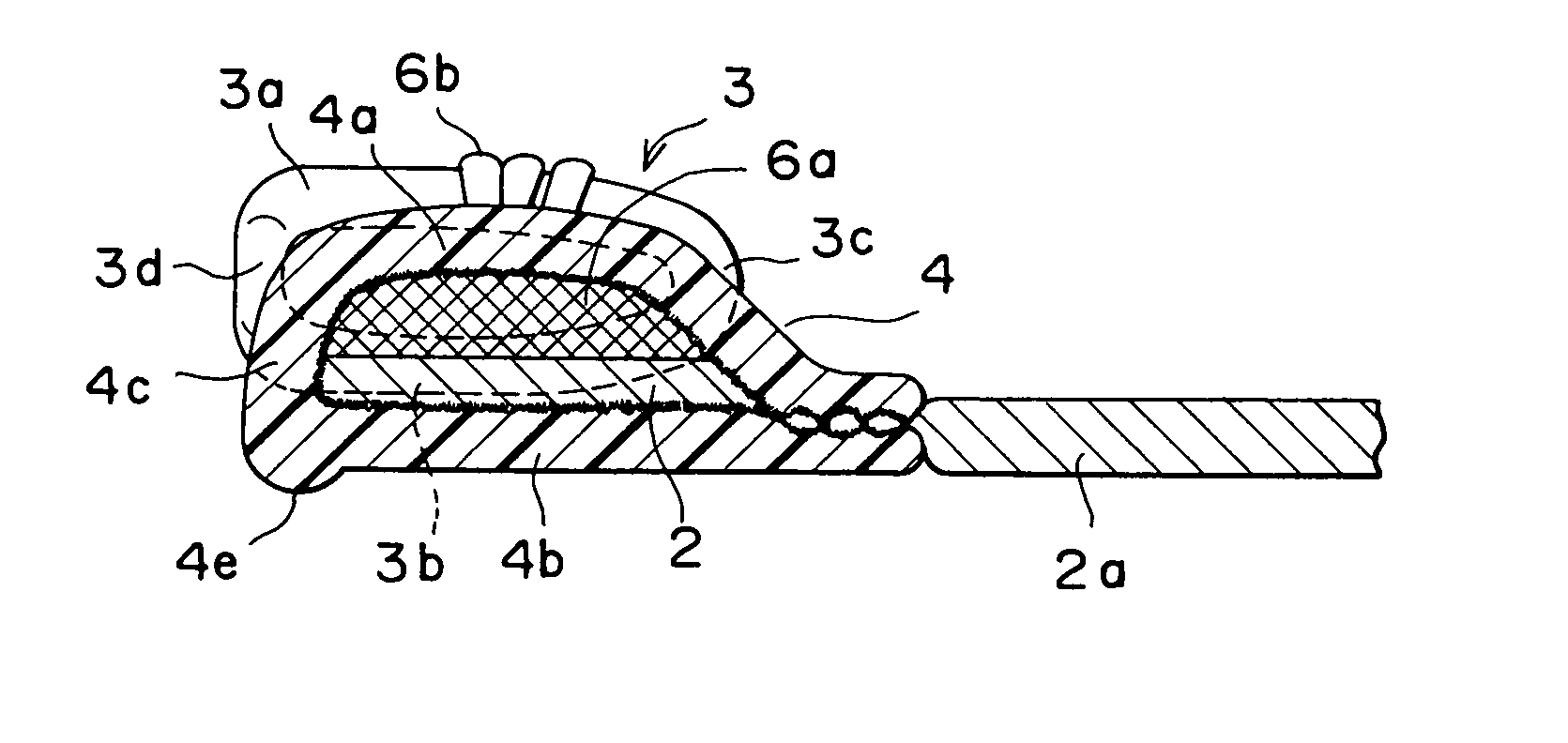
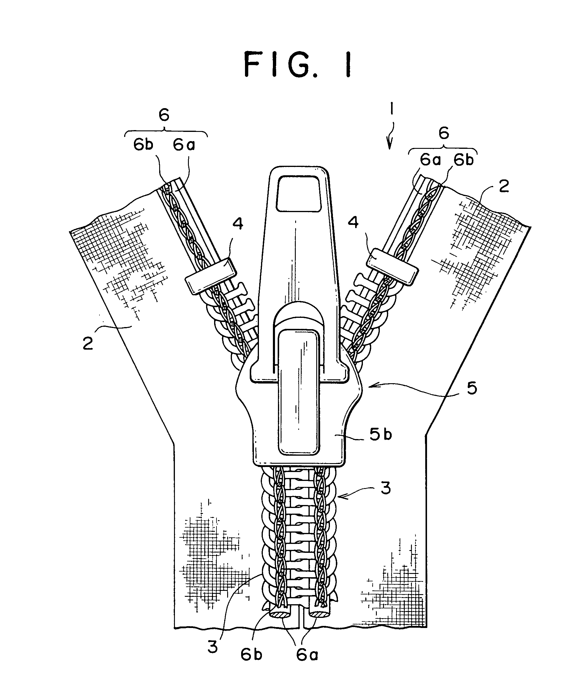
[0039] FIG. 4 shows a second embodiment which is a typical example of the invention. This embodiment concerns a slide fastener in which metallic fastener elements are attached individually along a side edge of the fastener tape 2. A side edge portion of the fastener tape 2 is nipped between a pair of the leg portions 3a and 3b of each fastener element 3 and by crimping the leg portions 3a, 3b inwardly, the fastener elements 3 are implanted on the side edge portion of the fastener tape 2.

first embodiment

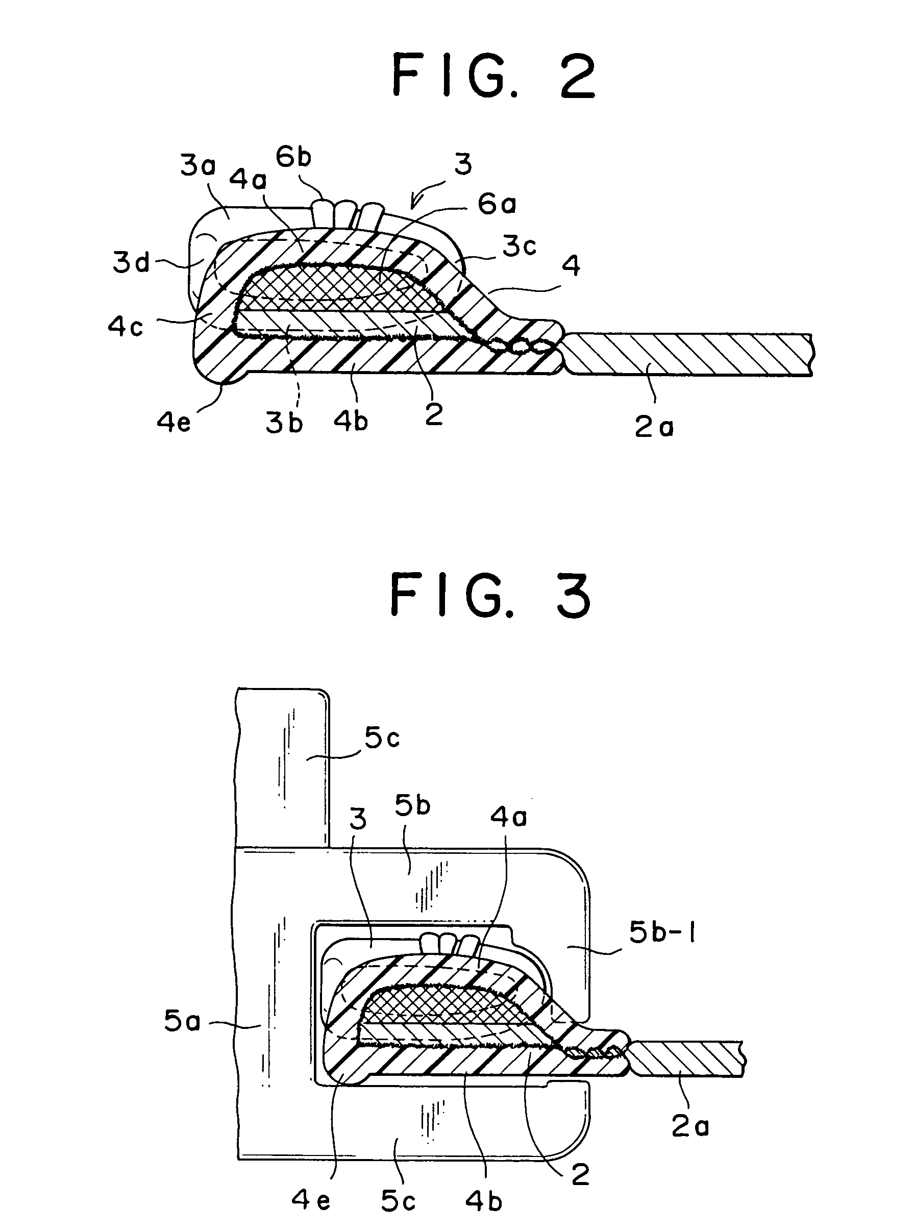
[0040] In this kind of the slide fastener 1, the upper and lower leg portions 3a, 3b of the fastener element 3 are symmetrical to each other. Thus, the slider 5 and the flanges 5b-1, 5c-1 of the upper and lower blades 5b, 5c are vertically symmetrical to each other. A protrusion 4f of this embodiment is formed on a vertex of the bent portion of the stopper portion 4. Like the above-described first embodiment, this protrusion 4f is formed in the form of a rib extended linearly in the length direction of the fastener tape 2. In case where, for example, the stopper portion 4 is molded integrally in the fastener tape 2 by heating with a heater, the protrusion 4f is molded by providing the vertex of the bent portion of upper and lower heater surfaces with a cavity for molding the protrusion.

[0041] When the slide fastener 1 is about to be closed by sliding the slider 5 in the slide fastener provided with the stopper portion 4 of this embodiment, the slider 5 reaches the stopper portion 4 ...


PUM


Abstract

A stopper portion has a minute protrusion on part of an outer peripheral face except a side face in the length direction of a fastener tape. This protrusion is a rib-like protrusion extended linearly in the length direction of the fastener tape formed on a vertex of the surface of a bent portion, a protrusion extended so as to be expanded in a curved shape in the length direction of the fastener tape or a rib-like protrusion protruded along a boundary portion between the bent portion of the stopper portion and a bottom face thereof. Existence of this protrusion not only reduces a sliding resistance when the slider is started but also eliminates prickly feeling and feeling of disharmony originating from a shape of an upper stopper which is a kind of the conventional stopper portion.

Description

[0001] 1. Field of the Invention[0002] The present invention relates to a slide fastener in which a stopper portion is molded on a slide fastener tape by melting a resin stopper material having a U-shaped section with a pressure by ultrasonic heating, high-frequency heating or heating with a heater adjacent to fastener elements attached on a side edge of the fastener tape.[0003] 2. Description of the Related Art[0004] Conventionally, as an upper stopper provided by melting resin material, generally, a film-like or monofilament-like material is attached on a top face of the fastener tape or fastener elements by welding means. For example in case of an upper stopper of a slide fastener disclosed in Japanese Patent Application Publication No. 48-37421, for example, monofilament made of thermoplastic synthetic resin such as polyester resin, or polyamide resin is cut out to a predetermined length and bent into a U shape and attached to an inverted portion or a leg portion of a coil-like ...

Claims


Application Information

Patent Timeline
Patent Type & Authority Applications(United States)
IPC IPC(8): A44B19/36A44B19/38
CPCA44B19/36A44B19/386Y10T24/2511Y10T24/2598Y10T24/2518
Inventor KONDO, NAOKIYOSHIDA, YONEOTOISHI, YOSHIYUKIMAEDA, HIDEJI
Owner YKK CORP
Why Eureka
Try Eureka