Specimen centrifuge system

Active Publication Date: 2004-05-13
IDS CO LTD
View PDF8 Cites 23 Cited by
  • Summary
  • Abstract
  • Description
  • Claims
  • Application Information

AI Technical Summary

Problems solved by technology

However, the apparatus requires a relatively large space because the first and second rotors need to be arranged together on the horizontal surface.
The apparatus i

Method used


Image

  • Specimen centrifuge system
  • Specimen centrifuge system
  • Specimen centrifuge system

Examples


first embodiment

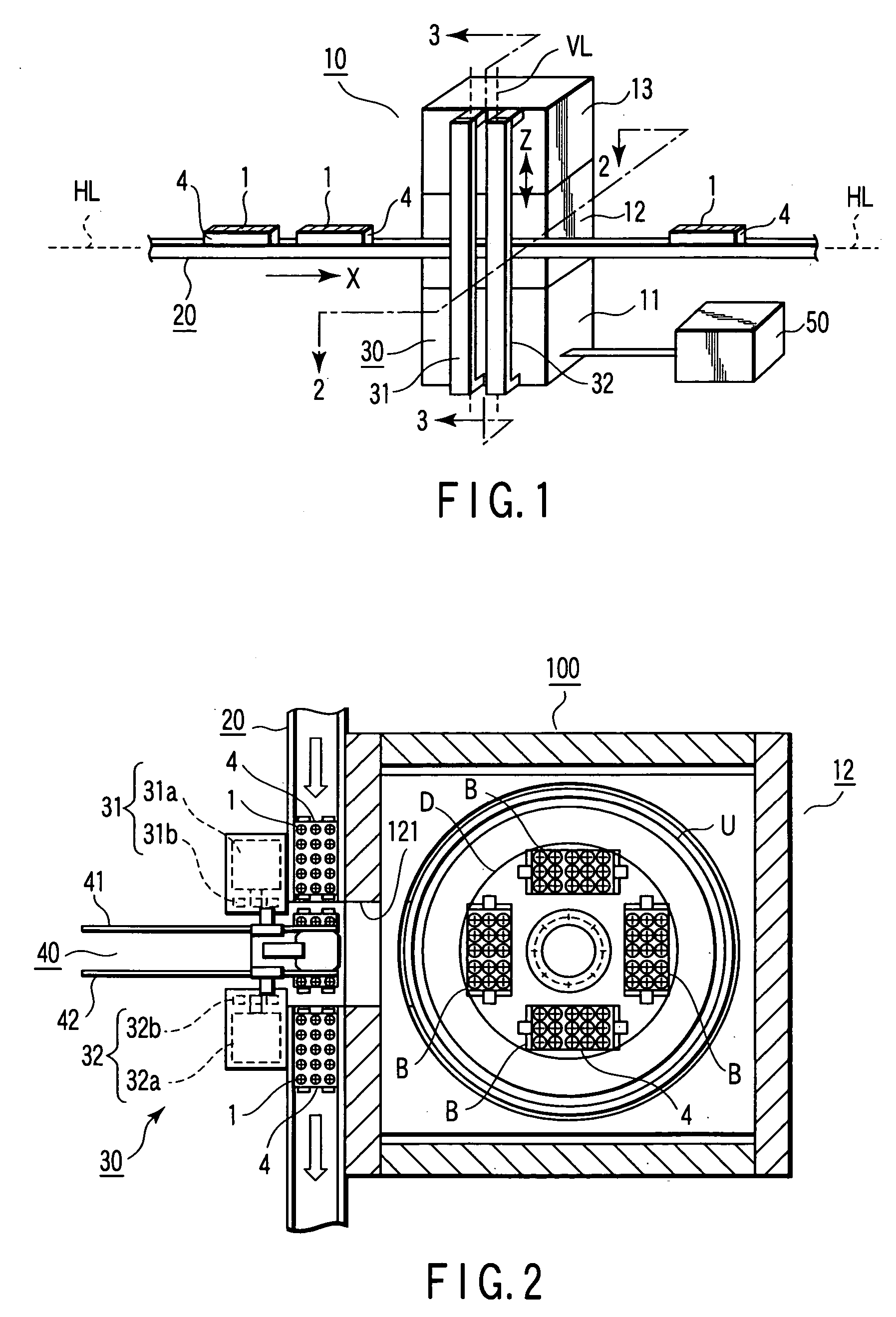
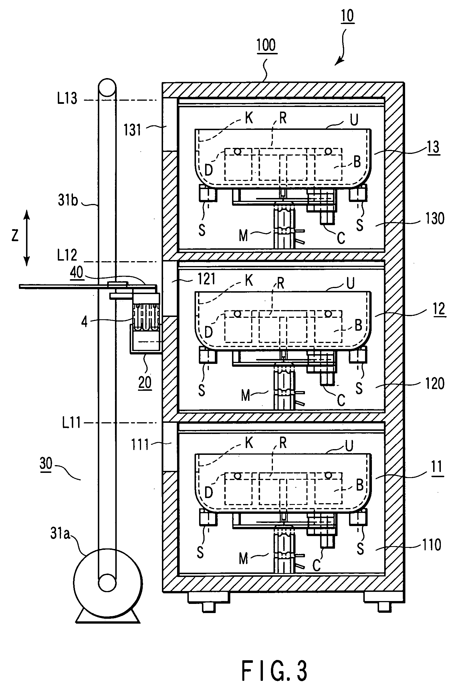
[0023] The rotor R has a plurality of buckets B (four in the first embodiment) near the circumference of a rotating disc D. The buckets B can store the specimen-container racks 2. The top ends of the buckets B are supported against the circumference of the disc D with shafts such that the buckets B can swing freely in their entirety. If the rotating disc D rotates at high speed, the bottoms of the buckets B are swung up in the radial direction of the disc D by centrifugal force.

[0024] The specimen centrifuges 11, 12 and 13 can be operated independently. A controller 50 controls a simultaneous operation and selective operation of the specimen centrifuges 11, 12 and 13. The controller 50 also controls the centrifuges 11, 12 and 13 that the rotation direction of the rotor R in each layer can be set in a given direction.

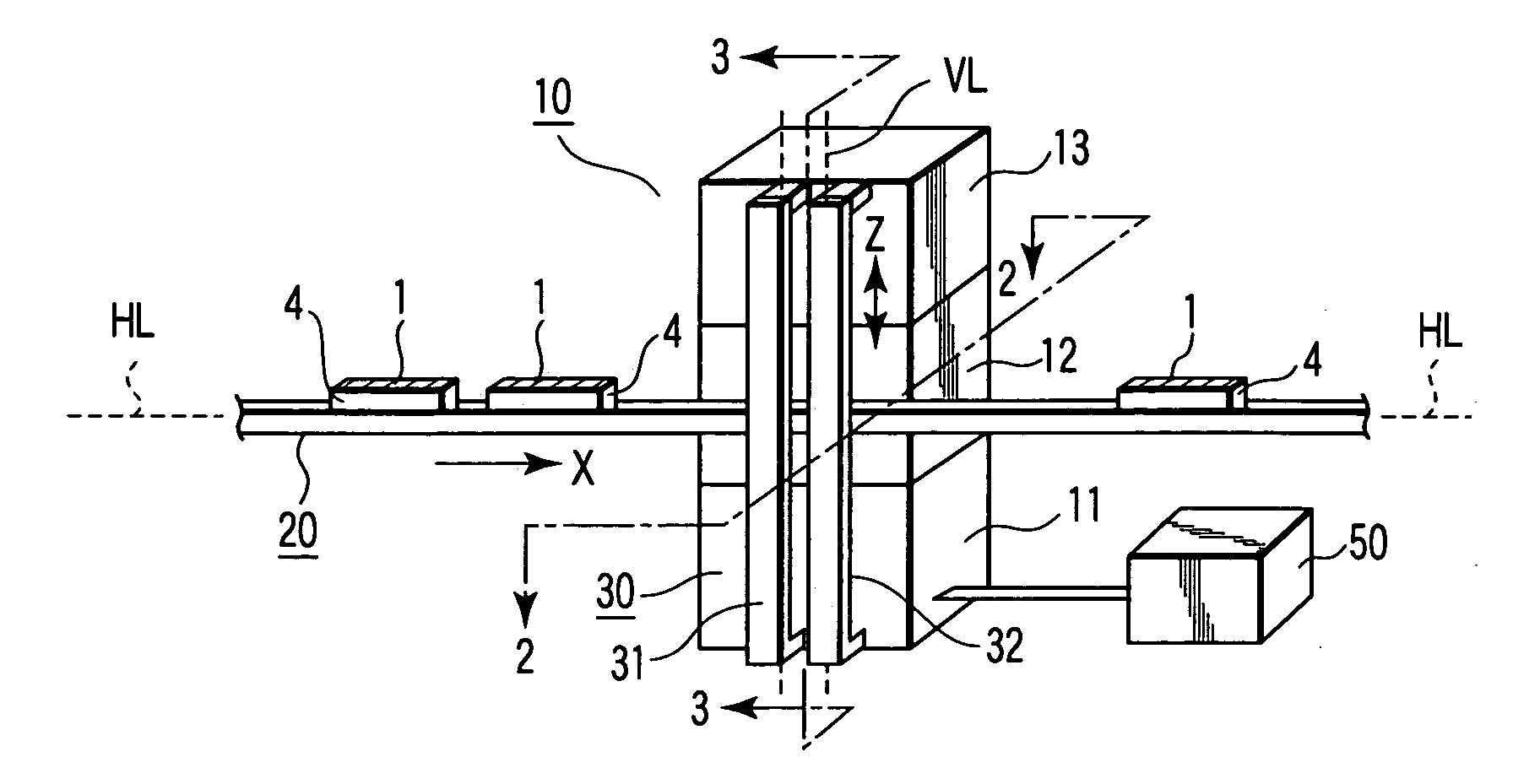
[0025] The cabinets 110, 120 and 130 have windows 111, 121 and 131 on their front walls. The specimen-container racks 4 can be inserted and removed through the windows 1...

second embodiment

[0037] FIG. 7 is a longitudinal sectional view showing a centrifuge unit 10 according to a second embodiment of the present invention. The second embodiment differs from the first embodiment in which specimen centrifuges 11, 12 and 13 are insertably and removably stored in their respective cabinets 110, 120 and 130 stacked in layers. More specifically, the rear walls of the cabinets 110, 120 and 130 are formed of lids 112, 122 and 132 (not shown) that can freely be opened and closed. Inner boxes 113, 123 and 133 containing the specimen centrifuges 11, 12 and 13 can be slid into and out of the cabinets 110, 120 and 130 in the directions of double-headed arrow P. Thus, for example, the specimen centrifuge 13 can be drawn out, as shown in FIG. 7, to perform predetermined maintenance.


PUM


Abstract

A specimen centrifuge system includes a centrifuge unit including a plurality of specimen centrifuges which are stacked in a plurality of layers in a vertical direction, a rack conveyor which is provided along a horizontal conveyance line, and a rack elevator which is provided along a vertical conveyance line. The rack elevator has a robot arm device which moves the specimen-container rack from the rack conveyor to the rack elevator and from the rack elevator to the rack conveyor and moves the specimen-container rack from the rack elevator to one of the specimen centrifuges and from one of the specimen centrifuges to the rack elevator.

Description

[0001] This application is based upon and claims the benefit of priority from the prior Japanese Patent Application No. 2002-318702, filed Oct. 31, 2002, the entire contents of which are incorporated herein by reference.[0002] 1. Field of the Invention[0003] The present invention relates to a specimen centrifuge system for use in a specimen testing center and the like.[0004] 2. Description of the Related Art[0005] A specimen centrifuge apparatus configured as follows is proposed as one for use in a specimen testing center and the like (see Jpn. Pat. Appln. KOKAI Publication No. 2000-84436). This apparatus includes first and second rotors. While one of the rotors is centrifuging a specimen, the other rotor replaces a specimen-contained tube with another one.[0006] The above specimen centrifuge apparatus is capable of centrifuging a specimen with efficiency. However, the apparatus requires a relatively large space because the first and second rotors need to be arranged together on the...

Claims


Application Information

Patent Timeline
IPC IPC(8): B04B5/02G01N1/10B04B5/04B04B5/10B04B11/00B04B13/00G01N35/00G01N35/04
CPCB04B5/0421B04B5/10B04B13/00B04B2011/046Y10T436/111666G01N2035/0465Y10T436/114165Y10T436/113332G01N2035/00504
Inventor ITOH, TERUAKI
Owner IDS CO LTD
Why Eureka
Try Eureka