Supercharge Your Innovation With Domain-Expert AI Agents!

Heat sink and combinations

a technology of heat sinks and combinations, applied in the direction of insulated conductors, power cables, cables, etc., can solve the problem of achieving the necessary heat transfer from increasingly confined spaces

Inactive Publication Date: 2004-05-20
LENOVO GLOBAL TECH INT LTD
View PDF2 Cites 1 Cited by
  • Summary
  • Abstract
  • Description
  • Claims
  • Application Information

AI Technical Summary

Problems solved by technology

Thus problems arise in effectuating the necessary transfers of heat from increasingly confined spaces.

Method used


Image

  • Heat sink and combinations
  • Heat sink and combinations
  • Heat sink and combinations

Examples


Embodiment Construction

[0009] While the present invention will be described more fully hereinafter with reference to the accompanying drawings, in which a preferred embodiment of the present invention is shown, it is to be understood at the outset of the description which follows that persons of skill in the appropriate arts may modify the invention here described while still achieving the favorable results of the invention. Accordingly, the description which follows is to be understood as being a broad, teaching disclosure directed to persons of skill in the appropriate arts, and not as limiting upon the present invention.

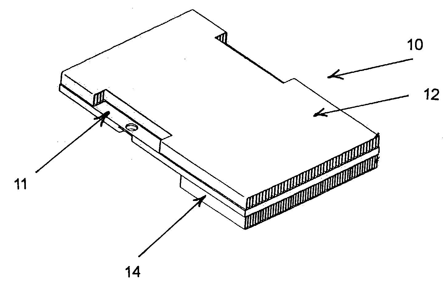
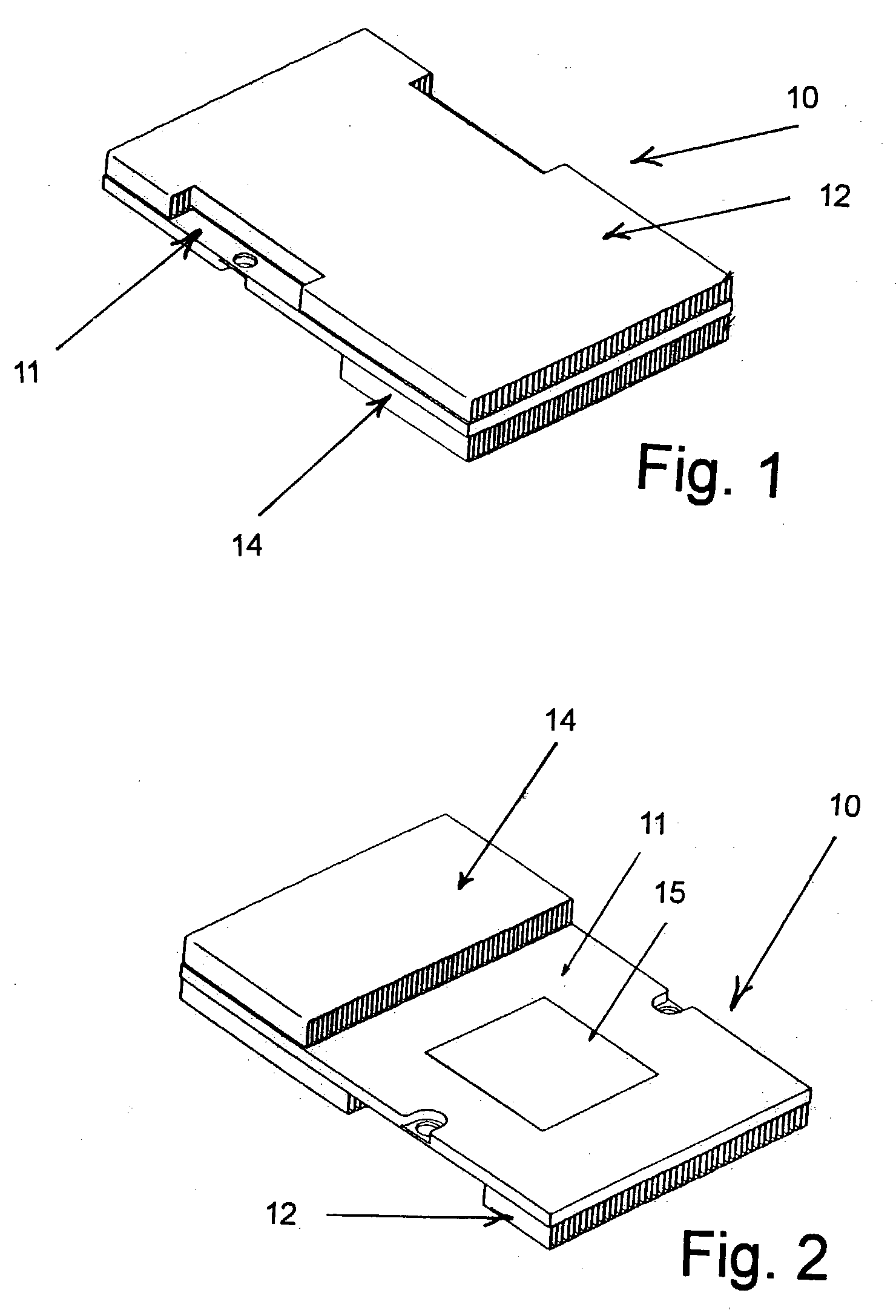
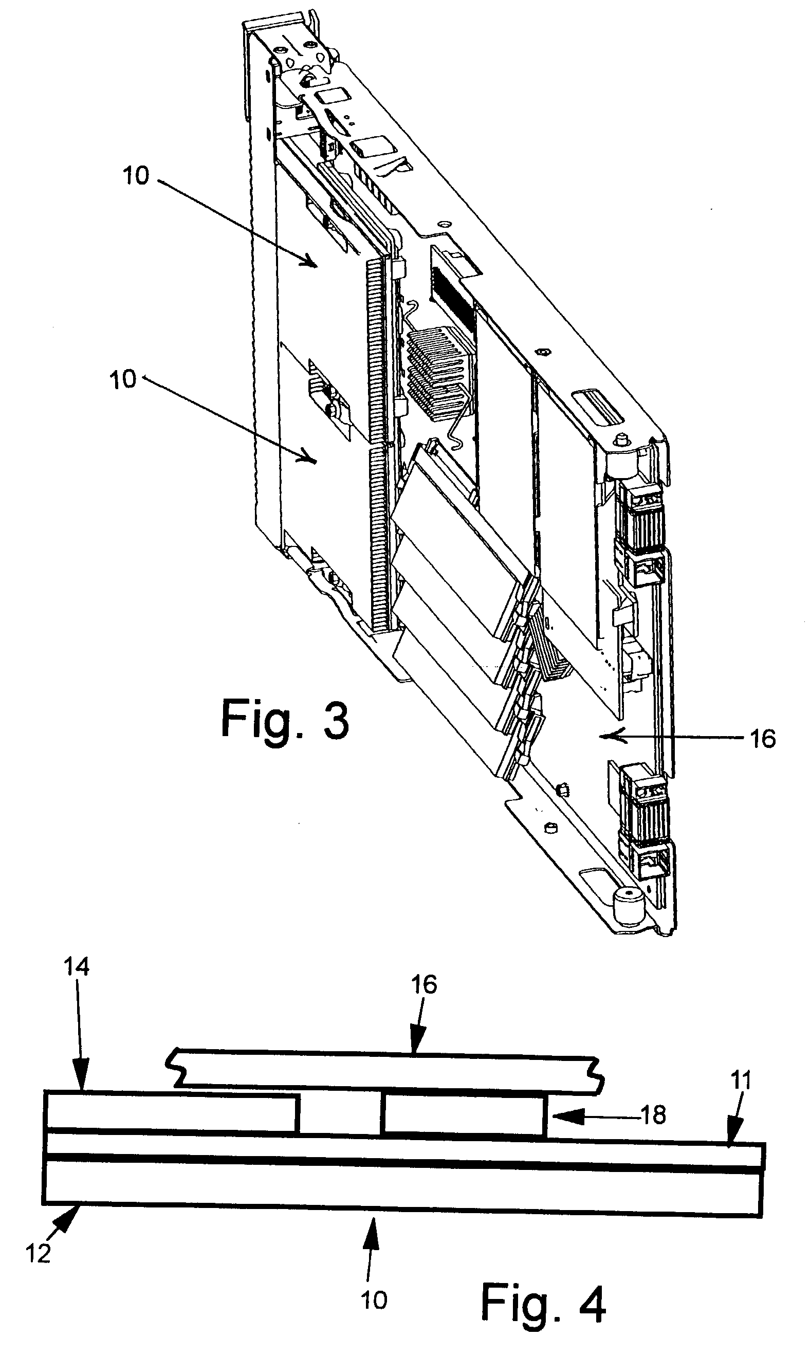
[0010] Referring now more particularly to the accompanying drawings, a heat sink in accordance with the present invention is there generally indicated at 10. The heat sink has a rectilinear body 11 of heat transferring material having opposing first and second broad surfaces, a first body of fins 12 affixed to the first broad surface and defining a first array of a plurality of elongate...


PUM


Abstract

The capability of an assembly to transfer heat from a semiconductor package source is enhanced while a reduction in the space required for effective operation is achieved. Bodies of fins defining tubular channels are affixed to oppositely facing surfaces of a rectilinear body which is adapted to receive heat from a semiconductor package.

Description

FIELD AND BACKGROUND OF INVENTION[0001] This invention relates to heat sinks for semiconductor packages and combinations of such a heat sink with devices from which heat must be transferred.[0002] The generation of heat within semiconductor packages for devices such as microprocessors has long been recognized as requiring heat transfer arrangements to permit satisfactory operation of computer circuits and the like. As the technology has progressed, heat loads imposed have risen which space allowances have compressed. Thus problems arise in effectuating the necessary transfers of heat from increasingly confined spaces. Recently, heat loads from microprocessor have risen to exceed seventy five watts, while space allowances have shrunk to limit the available height for a heat sink to less than forty millimeters.[0003] With the above problems in mind, it is a purpose of the present invention to enhance the capability of an assembly to transfer heat from a semiconductor package source wh...

Claims


Application Information

Patent Timeline
IPC IPC(8): H01L23/367H01L23/467
CPCH01L23/3672H01L23/467H01L2924/0002H01L2924/00
Inventor MATTESON, JASON AARONCRIPPEN, MARTIN JOSEPH
Owner LENOVO GLOBAL TECH INT LTD
Features
  • R&D
  • Intellectual Property
  • Life Sciences
  • Materials
  • Tech Scout
  • Unparalleled Data Quality
  • Higher Quality Content
  • 60% Fewer Hallucinations
Learn More