Controlling channel switching in a umts network

a control channel and channel switching technology, applied in the field of control channel switching in a umts network, can solve the problems of network operators' serious problems and inefficient use of utran resources

Inactive Publication Date: 2004-05-20
UNWIRED PLANET
View PDF0 Cites 25 Cited by
  • Summary
  • Abstract
  • Description
  • Claims
  • Application Information

AI Technical Summary

Benefits of technology

0015] A TCP sender is only able to take full advantage of a transmission channel in the UTRAN when the congestion window cwnd is equal to (or exceeds) the product of the bandwidth of the transmission channel and the round trip transmission delay between itself and the peer TCP node.

Problems solved by technology

This represents an inefficient use of UTRAN resources and a serious problem for network operators, especially where the number of CDMA spreading codes available to an operator is limited.

Method used


Image

  • Controlling channel switching in a umts network
  • Controlling channel switching in a umts network
  • Controlling channel switching in a umts network

Examples


Embodiment Construction

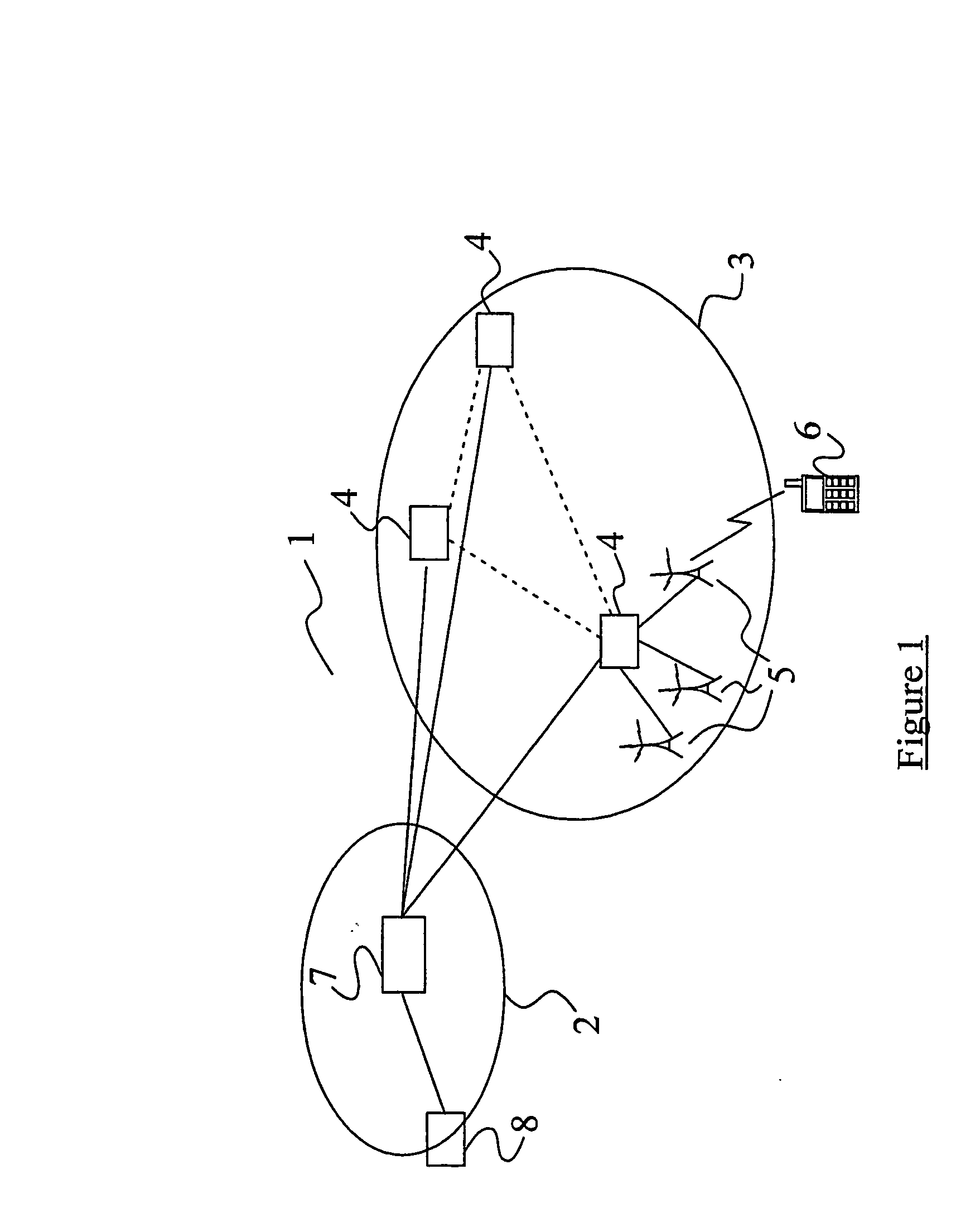
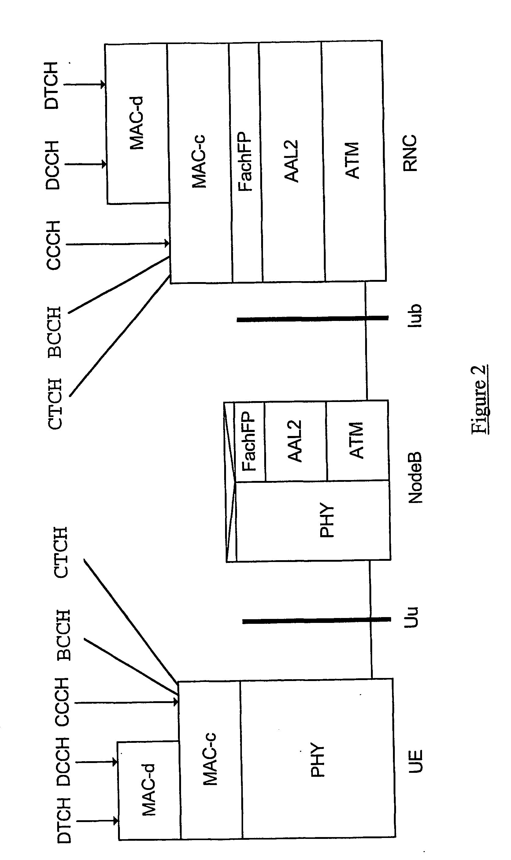
[0048] The general structure of a UMTS network has been described above with reference to the schematic drawing of FIG. 1. Protocol models for the FACH transport channel have also been described with reference to FIG. 2.

[0049] Considering the scenario illustrated in FIG. 2, and considering the transfer of data in the downlink direction, signalling and user data packets (e.g. IP packets) destined for the UE are passed, via a PDCP entity, to the Radio Link Control (RLC) entity. The RLC is responsible for the segmentation of packets (as well as for certain error correction and ciphering functions), and generates RLC Packet Data Units (PDUs) which are passed to the MAC layer and received as MAC Service Data Units (SDUs). The MAC-d entity schedules the packets for transmission.

[0050] Where a UE has been allocated a dedicated channel (DCH) or downlink shared channel (DSCH), the MAC-d PDUs are passed to the Node B for transmission over the air interface. However, where the UE has been allo...


PUM


Abstract

In a UMTS Terrestrial Radio Access Network (UTRAN), a method of switching from a current common channel to a dedicated channel for a UE. The method comprises estimating the round trip delay for data packets travelling between the UE and a peer node with which the UE is communicating. The product of the estimated round trip delay and the bandwidth of the common channel or the dedicated channel is determined and a threshold defined on the basis of that product. A switch from the common channel to a dedicated channel is initiated when the fill level of the RLC buffer(s) in the UTRAN for the UE reaches or exceeds said threshold.

Description

[0001] The present invention relates to channel switching in a Universal Mobile Telecommunications System (UMTS) network and more particularly to controlling channel switching to optimise the use of transmission resources.[0002] The European Telecommunications Standardisation Institute (ETSI) is currently in the process of standardising a new set of protocols for mobile telecommunications systems. The set of protocols is known collectively as Universal Mobile Telecommunications System (UMTS).[0003] FIG. 1 illustrates schematically a UMTS network 1 which comprises a core network 2 and a UMTS Terrestrial Radio Access Network (UTRAN) 3. The UTRAN 3 comprises a number of Radio Network Controllers (RNCs) 4, each of which is coupled to a set of neighbouring Base Transceiver Stations (BTSs) 5. BTSs are sometimes referred to as Node Bs. Each Node B 5 is responsible for a given geographical cell and the controlling RNC 4 is responsible for routing user and signalling data between that Node B...

Claims


Application Information

Patent Timeline
Patent Type & Authority Applications(United States)
IPC IPC(8): H04L12/56H04W28/14H04W36/06
CPCH04W36/06H04W28/14
Inventor MEYER, MICHAELSACHS, JOACHIMWAGER, STEFANMATINMIKKO, REIJOWIGELL, TOOMASPEISA, JANNEVAN DER POL, EDWIN
Owner UNWIRED PLANET
Why Eureka
Try Eureka