
Method for skin/surface abrasion

a skin technology, applied in the field of skin or surface abrasion apparatus and methods, can solve the problems of relatively painful and messy process, and relatively messy procedur

Inactive Publication Date: 2004-05-20
EDGE SYST CORP
View PDF28 Cites 97 Cited by
  • Summary
  • Abstract
  • Description
  • Claims
  • Application Information

AI Technical Summary

Benefits of technology

The handpiece effectively abrades the skin while maintaining a clean environment by removing debris through suction, reducing pain and mess, and allowing for adjustable abrasion levels with disposable elements, enhancing user experience and treatment efficacy.

Problems solved by technology

This process tends to be relatively painful and messy.
This is also a fairly messy procedure since the abrasion takes place outside of the handpiece.

Method used


Image

  • Method for skin/surface abrasion
  • Method for skin/surface abrasion
  • Method for skin/surface abrasion

Examples


Embodiment Construction

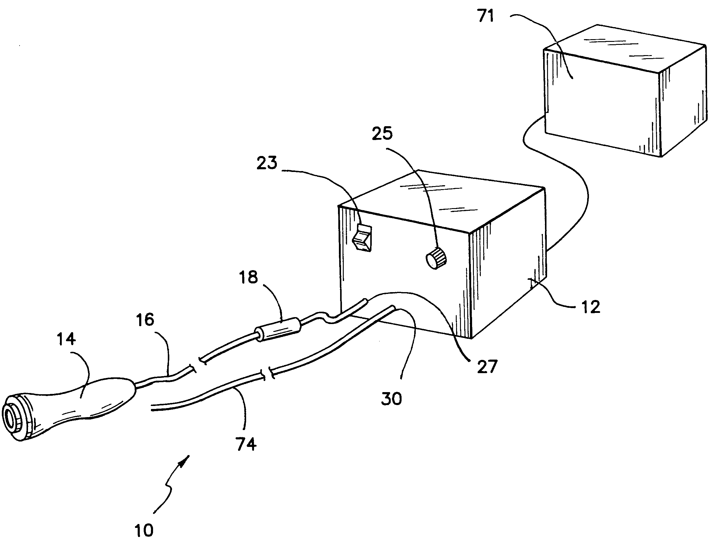
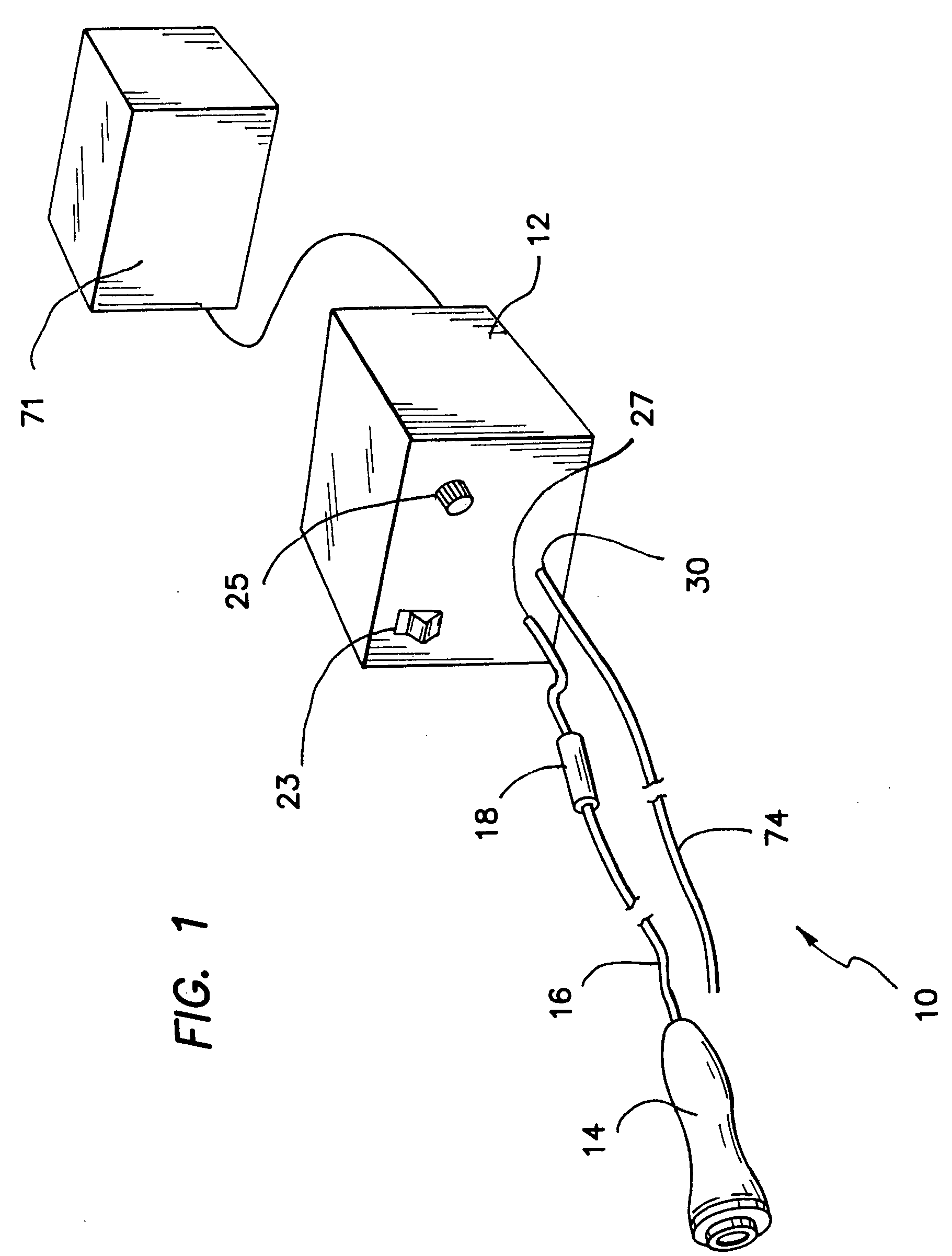
[0021] A dermabrader is illustrated in FIG. 1 and designated by the reference numeral 10. The dermabrader 10 includes a console 12, and a handpiece 14 connectable to the console 12 through a vacuum tube 16 having an inline filter 18. The console 12 in this case is powered by a 12 volt transformer 21 and includes a power switch 23 and a vacuum adjustment 25. Releasable connectors are provided at a vacuum port 27 and a pressure port 30 discussed in greater detail below.

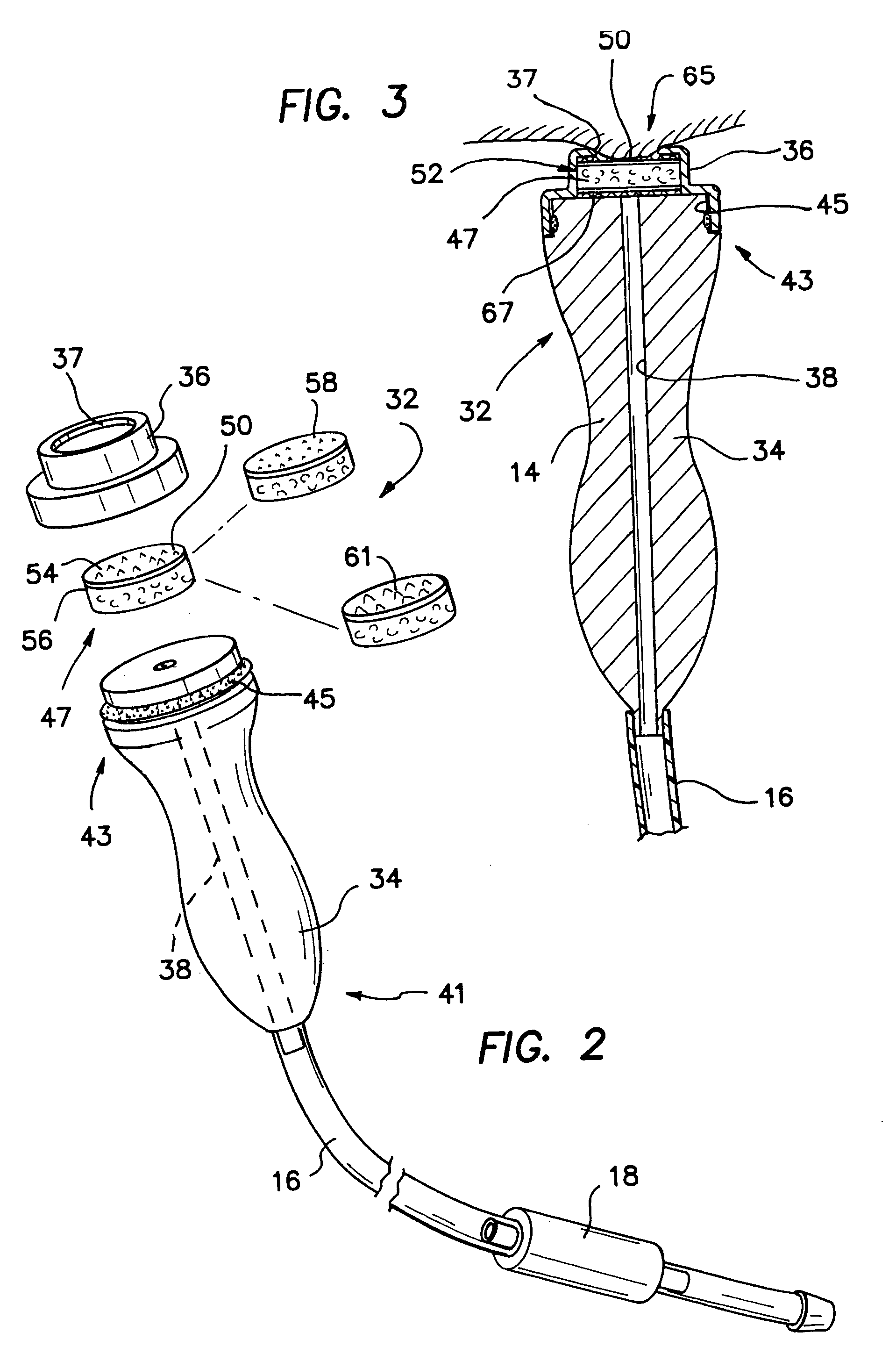
[0022] The handpiece 14, which is shown in the exploded view of FIG. 2, includes a housing 32 which in this embodiment is formed by base 34 and a cap 36 having an opening 37. The base 34 has a central channel 38 extending between a proximal end 41 and a distal end 43. At the proximal end 41, the channel 38 is coupled to the vacuum tube 16; at the distal end 43, the cap 36 is attached to the base 34 in a snap-fit relationship. This configuration is facilitated by provision of an O-ring 45 at the distal end 43.

[0023] Of p...


PUM


Abstract

A dermabrasion handpiece adapted for use to abrade the skin of a patient includes a housing extending along an axis between a proximal end and a distal end. Portions of the housing define a hole at the distal end with an abrasion element disposed in the housing in proximity to the hole. The housing is adapted for connection to a vacuum source to pull a portion of the skin through the hole and to move the skin portion into contact with the abrasion element. Movement of the abrader relative to the skin abrades tissue from the skin portion extending through the hole. The abrader can be provided in the form of a roller or blade moveable relative to the housing to abrade the skin. The abrasion element can be selected from a series of elements each having different abrasion characteristics and can be mounted in either the cap or the base of the housing.

Description

[0001] 1. Field of the Invention[0002] This invention relates generally to skin or surface abrasion apparatus and methods, and more specifically to semi-automatic handpieces used in dermabrasion.[0003] 2. Discussion of the Prior Art[0004] It is often desirable to abrade the outer layer or epidermis of the skin in order to smooth or blend scars, or blemishes caused by acne for example. The techniques employed have been separated generally into two fields referred to as dermabrasion and microdermabrasion. With microdermabrasion, a sand or grit is carried by an airflow that is directed against the skin. The momentum of the grit tends to wear away two to three cell layers of the skin with each pass of a handpiece.[0005] Dermabrasion refers generally to the mechanical movement of an abrasive element against the skin. A handpiece is employed which may include a pneumatic or electric motor which drives the abrasive element typically in the form of a burr, wheel, or disk. This process tends...

Claims


Application Information

Patent Timeline
Patent Type & Authority Applications(United States)
IPC IPC(8): A61B17/00A61B17/32A61B17/54
CPCA61B17/54A61B2017/00535A61B2017/320012A61B2017/00761A61B2017/00561
Inventor IGNON, ROGER G.
Owner EDGE SYST CORP
Learn More