Electrical Dermabrasion Device

a technology of electric dermabrasion and electrodes, which is applied in the direction of surgical forceps, applications, manufacturing tools, etc., can solve the problems of inconvenient use, inconvenient use, and high probability of wound infection, so as to reduce the time required for exfoliation, prevent contamination of abrasion plates to be brought into contact with the skin, and minimize the dispersion of exfoliated skin pieces

Inactive Publication Date: 2007-09-27
CHO
View PDF24 Cites 17 Cited by
  • Summary
  • Abstract
  • Description
  • Claims
  • Application Information

AI Technical Summary

Benefits of technology

[0007] As described above, the electrical dermabrasion devices in accordance with the present invention can solve the problems of the conventional dermabrasion device. That is, since the conventional dermabrasion device has to be rubbed over the skin repetitively using a physical force of a user, the user feels tired easily. Since, however, the inventive dermabrasion device is electrically operated by using the motor, it is unlikely that the user feels exhausted even after a long-time use thereof. Further, the time required for the exfoliation can be greatly reduced due to the high-speed rotation of the motor, and the dispersion of exfoliated skin pieces can be minimized by collecting them in the skin piece storages in the rotary plate or the skin pieces collecting vessel, thereby exhibiting a sanitary advantage. Moreover, by providing the cover for closing the main body, the contamination of the abrasion plate to be brought into contact with the skin can be prevented while facilitating the transporting of the dermabrasion device.

Problems solved by technology

In case the hardened layer of the skin cracks, a person may feel painful and there is a high likelihood that the wound is infected by the invasion of germs in the cracks.

Method used


Image

  • Electrical Dermabrasion Device
  • Electrical Dermabrasion Device
  • Electrical Dermabrasion Device

Examples


first embodiment

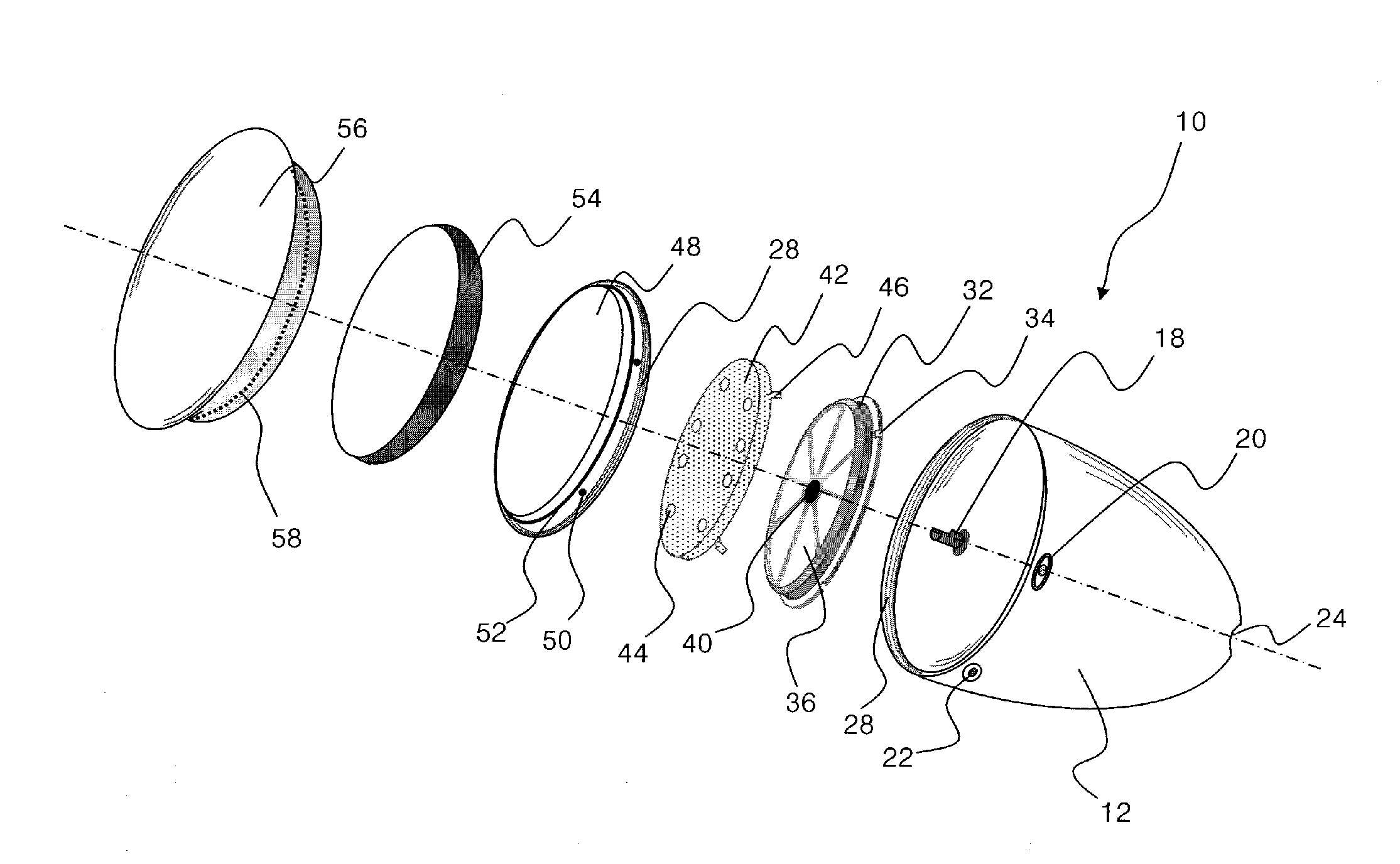
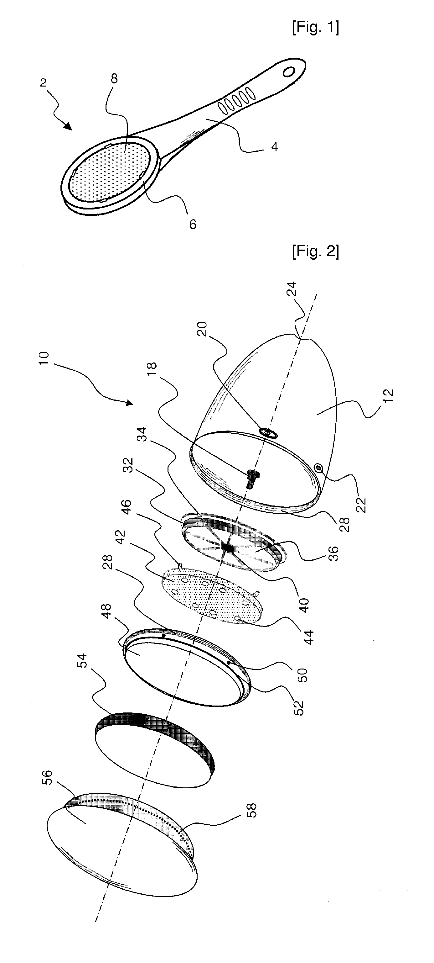
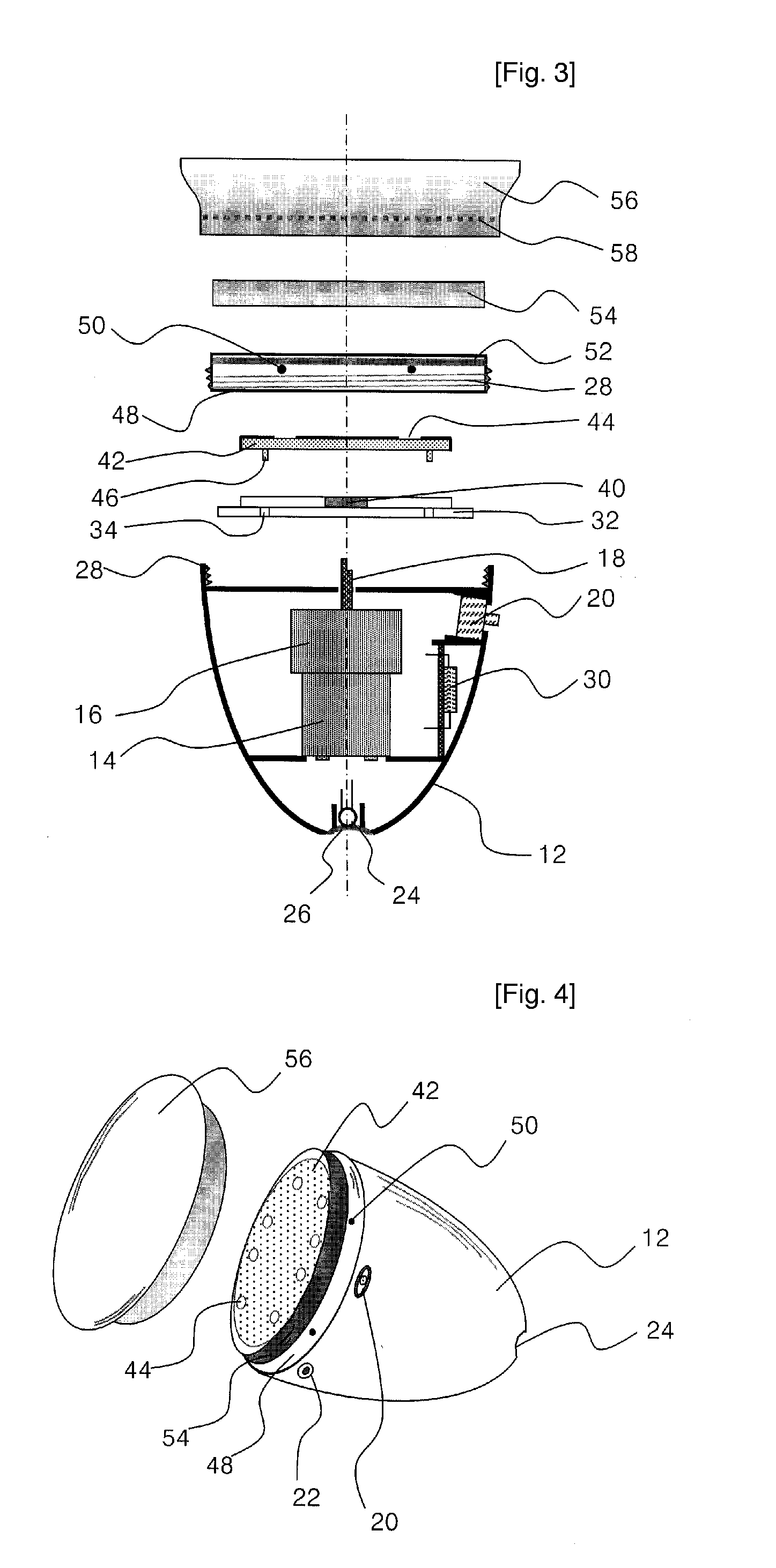
[0049] Referring to FIGS. 12 to 20, there is illustrated an electrical dermabrasion device 100 in accordance with a second preferred embodiment of the present invention. As shown therein, the electrical dermabrasion device 100 includes a hollow main body 120 having a handle 110 attached thereto, an abrasion unit installed at one side of the main body 120 to remove hardened skin, and a driving unit incorporated in the hollow portion of the main body 120 to rotate the abrasion unit. Though not shown, the electrical dermabrasion device 100 may further include a cover detachably connected to the main body 120 to selectively expose the abrasion unit, as in the above-described first embodiment of the present invention.

[0050] As in the first embodiment, the main body 120 is of an oval shape, and the handle 110 is attached to a lower portion thereof. Further, the inside of the handle 110 is utilized as a brush storage 112 for storing therein a brush for cleaning, etc.

[0051] The driving uni...

second embodiment

[0060] The electrical dermabrasion device 100 with the above-described configuration in accordance with the second embodiment is operated as follows. If the switch 118 is turned on after supplying power using an adapter (not shown), the first and the second motor 114 and 116 are driven. By the rotation of the first motor 114, the first impeller 132 and the rotary plate 130 connected to the first motor shaft 136 are rotated, whereby the abrasion plate 140 installed on top of the rotary plate 130 is also rotated, so that exfoliation is performed. The switch 118 is used to control the rotational speed of the first motor 114 as well as to supply the power to the dermabrasion device 100. Thus, by adjusting the rotational speed of the abrasion plate 140 depending on the state of the to-be-exfoliated skin of the foot by means of the switch 118, effective exfoliation can be performed without causing a wound on the foot. Though the abrasion plate 140 is rotated at a high speed, it can be pre...


PUM


Abstract

An electrical dermabrasion device for exfoliating a foot includes a hollow main body; an abrasion unit connected to the main body, for exfoliating the foot; and a driving unit incorporated in a hollow portion of the main body, for rotating the abrasion unit.

Description

TECHNICAL FIELD [0001] The present invention relates to an electrical dermabrasion device; and, more particularly, to an electrical dermabrasion device for removing a hard, dry skin layer on a heel, a sole, a lateral surface and toes of the foot by abrading them. BACKGROUND ART [0002] In general, the human skin can be divided into soft and hard areas. For example, a face or a hand directly exposed to the air without contacting other objects are soft, and a leg or a breast on which no strong pressure is imposed are also apt to be soft though they are not directly exposed to the air by being covered with cloths. In contrast, the skin of a foot comes into a direct contact with a hard surface of shoes for a long time while a person stands or walks, so a part of the foot skin becomes hardened, forming a dry, hardened layer of the skin. This dry, hardened skin layer is thickened with the lapse of time, or even cracked. In case the hardened layer of the skin cracks, a person may feel painf...

Claims


Application Information

Patent Timeline
Patent Type & Authority Applications(United States)
IPC IPC(8): A61B17/50A61B17/00A61B17/28A61B17/54A61B19/00A61M1/00
CPCA61B17/54A61B19/36A61B2217/005A61B2017/00876A61B2017/2925A61B2017/00398A61B90/80
Inventor CHO, GYUNG SU
Owner CHO
Why Eureka
Try Eureka