Method of and system for testing equipment during manufacturing

a technology for manufacturing equipment and equipment, applied in the field of equipment testing, can solve the problems of increasing complexity of mobile terminals used in the system, and increasing the number of redundant softwar

Inactive Publication Date: 2004-05-27
UNWIRED PLANET
View PDF41 Cites 60 Cited by
  • Summary
  • Abstract
  • Description
  • Claims
  • Application Information

AI Technical Summary

Problems solved by technology

Since cellular telecommunications systems were first introduced in the 1980s, mobile terminals utilized in the systems have become increasingly complex.
These demands are further increased by the fact that a mobile terminal is a resource-scarce environment that is relatively li

Method used


Image

  • Method of and system for testing equipment during manufacturing
  • Method of and system for testing equipment during manufacturing
  • Method of and system for testing equipment during manufacturing

Examples


Embodiment Construction

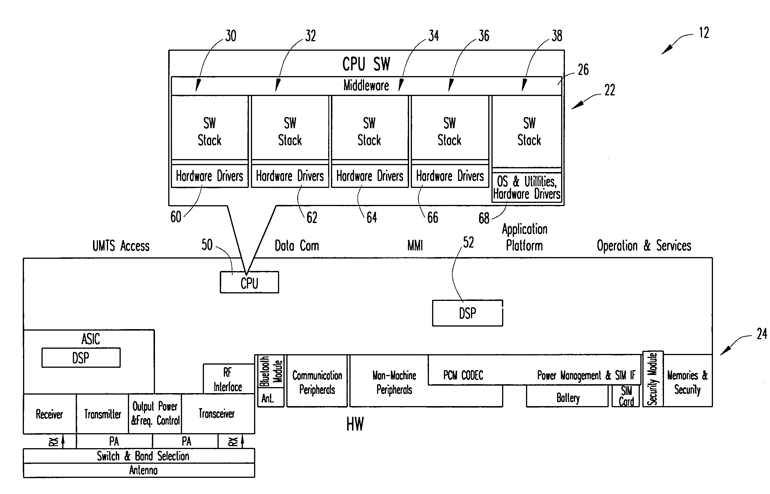
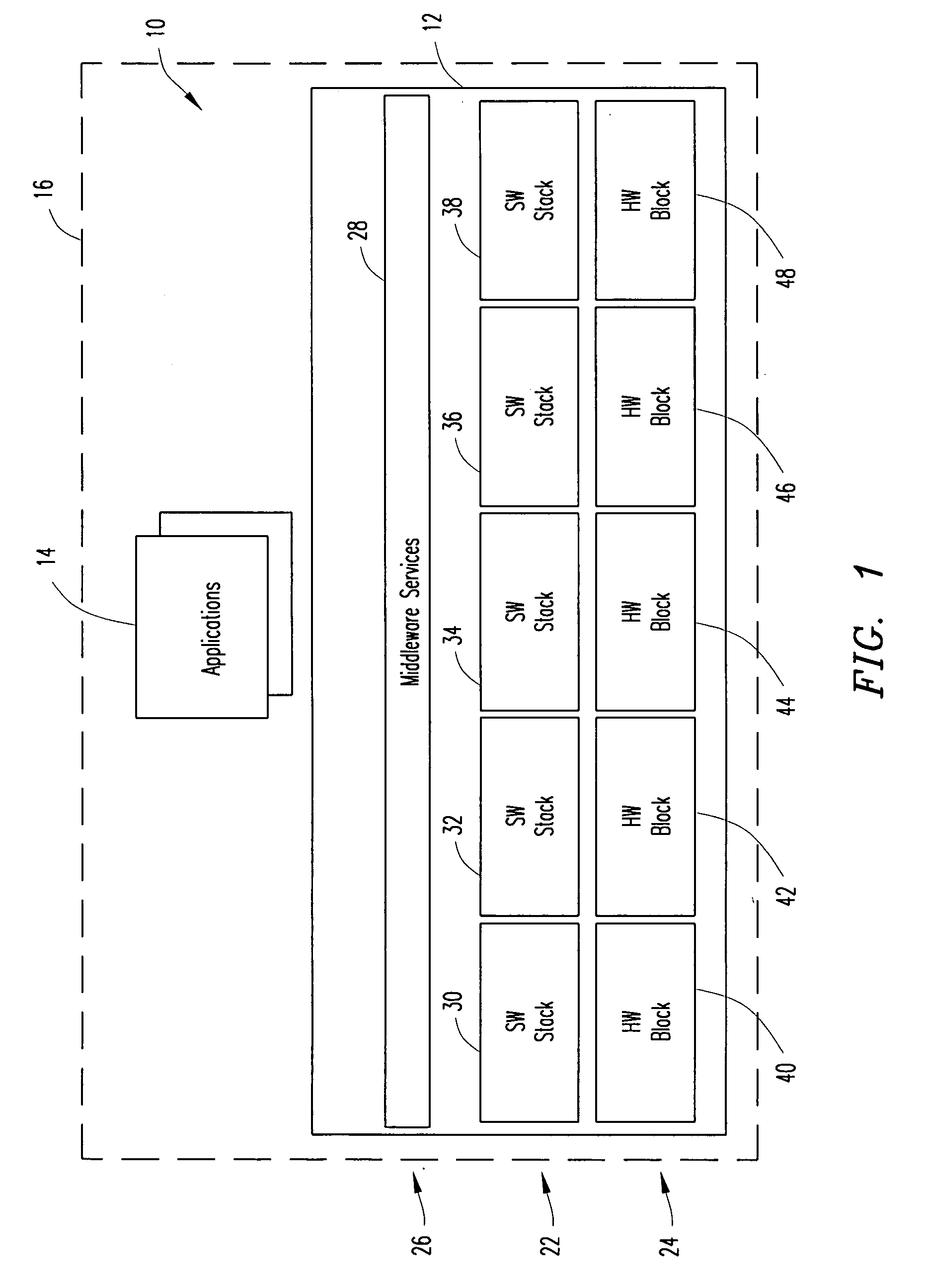
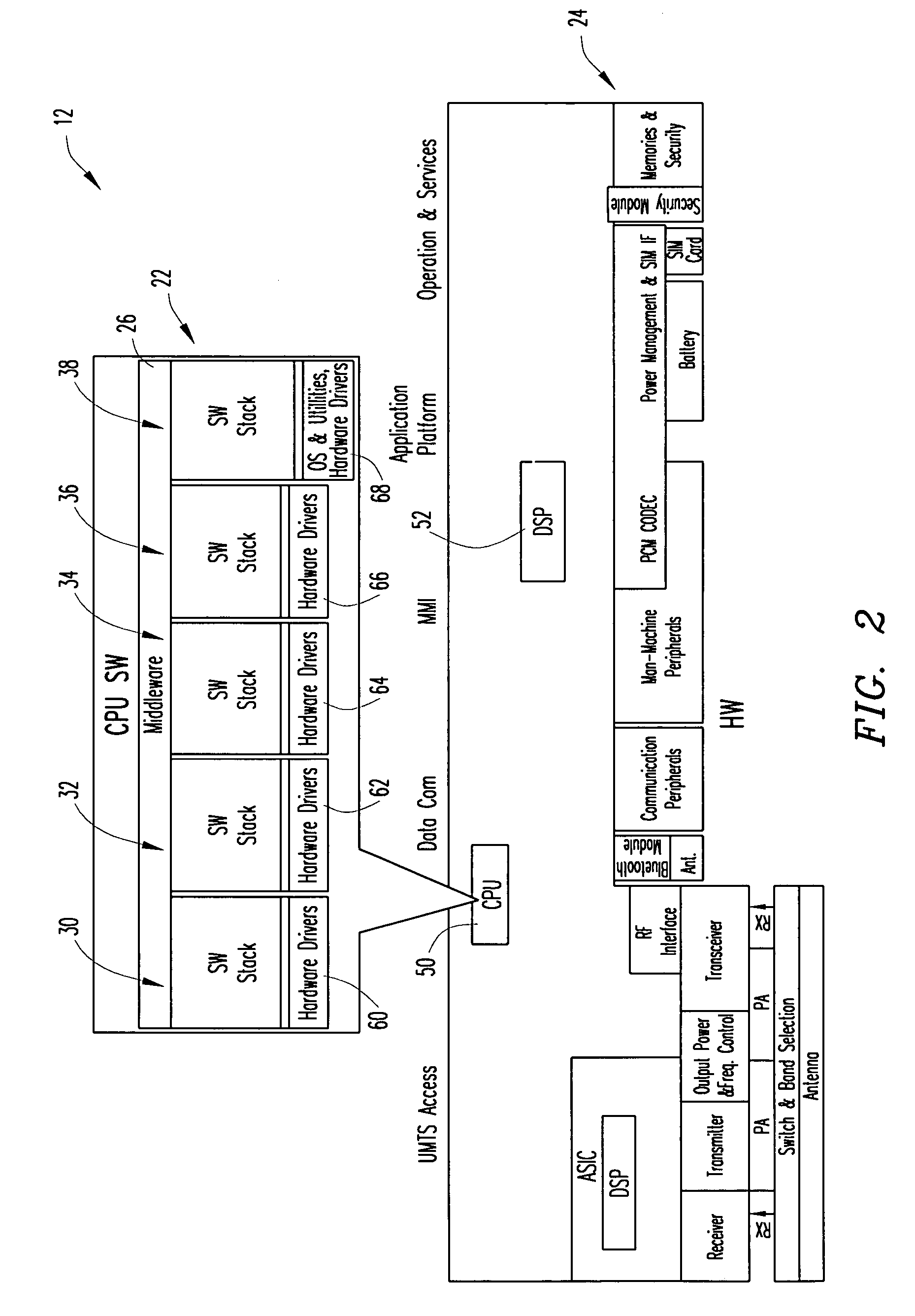
[0020] FIG. 1 is a block diagram that schematically illustrates a platform system 10 for a mobile terminal for a wireless telecommunications system in accordance with principles of the present invention. The platform system 10 includes a mobile-terminal platform assembly 12 and application software (i.e., one or more applications) 14 that have been loaded, installed, and run in the mobile-terminal platform assembly. The platform system 10 is adapted to be incorporated in a mobile terminal 16, the mobile terminal 16 being generally designated by a dotted line. The mobile-terminal platform assembly 12 includes a software services component 22, a hardware component 24, and an interface component 26.

[0021] The software services component 22 includes at least one well-structured functional software unit for providing services that are offered to users via the interface component 26. In the exemplary embodiment illustrated in FIG. 1, the at least one software unit includes five vertically...


PUM


Abstract

A platform system for a mobile terminal for a wireless telecommunications system includes a mobile-terminal platform assembly. The mobile-terminal platform assembly includes a software services component having at least one functional software unit, a hardware component having at least one hardware unit associated with and controlled by the at least one functional software unit, and an interface component having at least one interface for providing access to the mobile-terminal platform assembly. The platform system also includes test application software loaded, installed, and run on the mobile-terminal platform assembly via the interface component. The test application software tests both software and hardware of the mobile terminal during both production testing and testing performed during a lifecycle of the mobile terminal. The test application software may be located in an unprotected code space of the mobile terminal in order to allow the test application software to be overwritten as needed to make space for other applications.

Description

[0001] This patent application is a continuation-in-part of co-pending U.S. patent application Ser. No. 10 / 359,835, which was filed on Feb. 7, 2003. U.S. patent application Ser. No. 10 / 359,835 claims the benefit of priority from U.S. Provisional Patent Application No. 60 / 357,366, filed on Feb. 15, 2002, U.S. Provisional Patent Application No. 60 / 357,291, filed on Feb. 15, 2002, U.S. Provisional Patent Application No. 60 / 412,756, filed on Sep. 23, 2002, U.S. Provisional Patent Application No. 60 / 412,763, filed on Sep. 23, 2002, and U.S. Provisional Patent Application No. 60 / 412,875, filed on Sep. 23, 2002. This patent application incorporates by reference the entire disclosures of each of U.S. patent application Ser. No. 10 / 359,835, U.S. Provisional Patent Application No. 60 / 357,366, U.S. Provisional Patent Application No. 60 / 357,291, U.S. Provisional Patent Application No. 60 / 412,756, U.S. Provisional Patent Application No. 60 / 412,763, and U.S. Provisional Patent Application No. 60 / ...

Claims


Application Information

Patent Timeline
IPC IPC(8): H04B17/00H04M3/00H04W24/06
CPCH04W24/06
Inventor MOLLER, BERNDSOLVE, TORBJORNMEDINA-WARMBURG, CRISTIAN
Owner UNWIRED PLANET
Why Eureka
Try Eureka