Sealing apparatus and manufacturing process of soft article having sealed portion

Inactive Publication Date: 2004-06-03
UNI CHARM CORP
View PDF10 Cites 32 Cited by
  • Summary
  • Abstract
  • Description
  • Claims
  • Application Information

AI Technical Summary

Problems solved by technology

Accordingly, moving speed of the ultrasonic horn is varied depending upon production speed to vary a time among a pressure and the time as sealing conditions to make it difficult to achieve good seal.
Accordingly, when the production speed is to be varied after production of the sealing apparatus, an allowable range for varying the production speed is structurally quite limited.
Therefore, difficulty is encountered in achieving uniform ultrasonic

Method used


Image

  • Sealing apparatus and manufacturing process of soft article having sealed portion
  • Sealing apparatus and manufacturing process of soft article having sealed portion
  • Sealing apparatus and manufacturing process of soft article having sealed portion

Examples


first embodiment

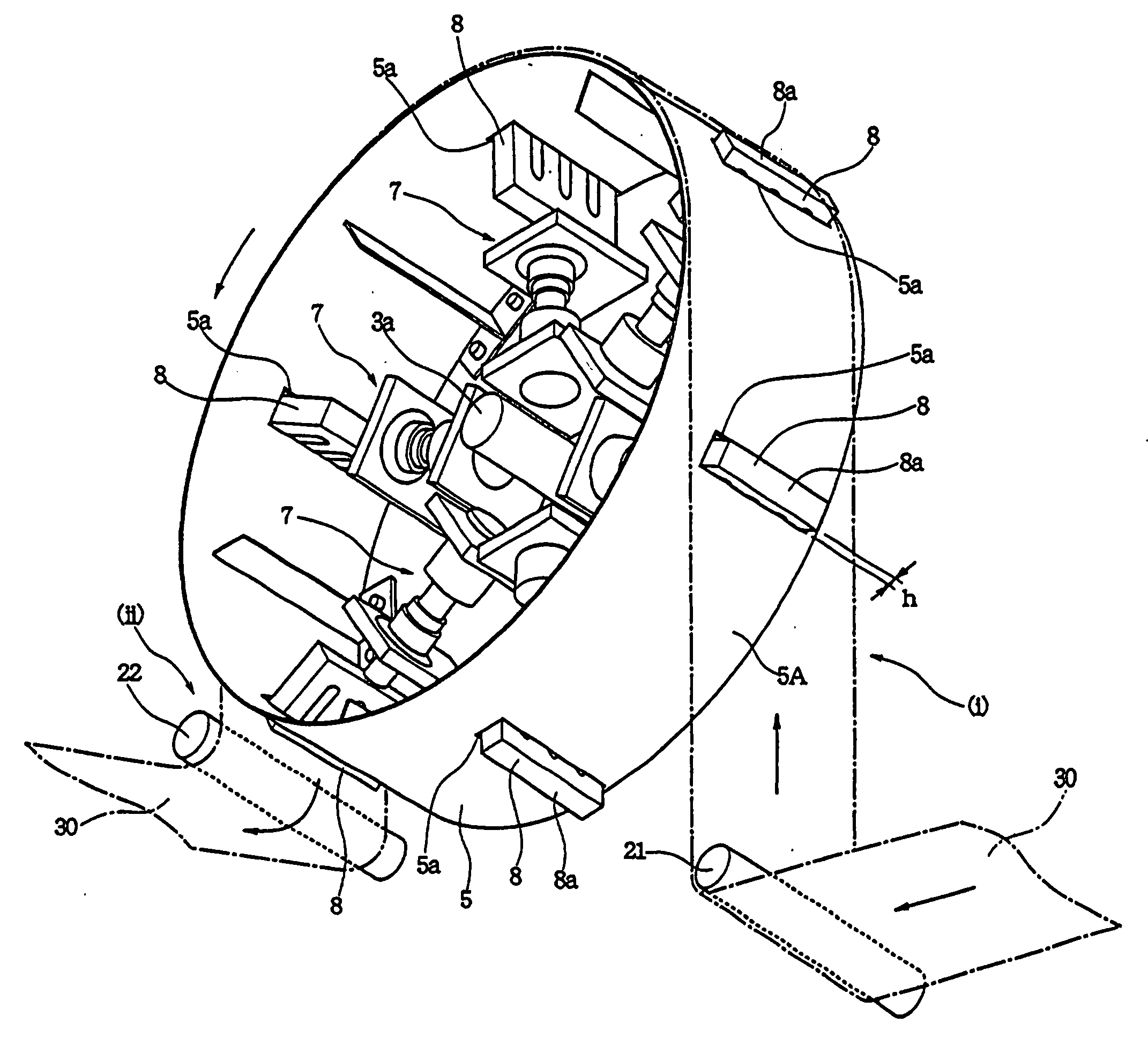
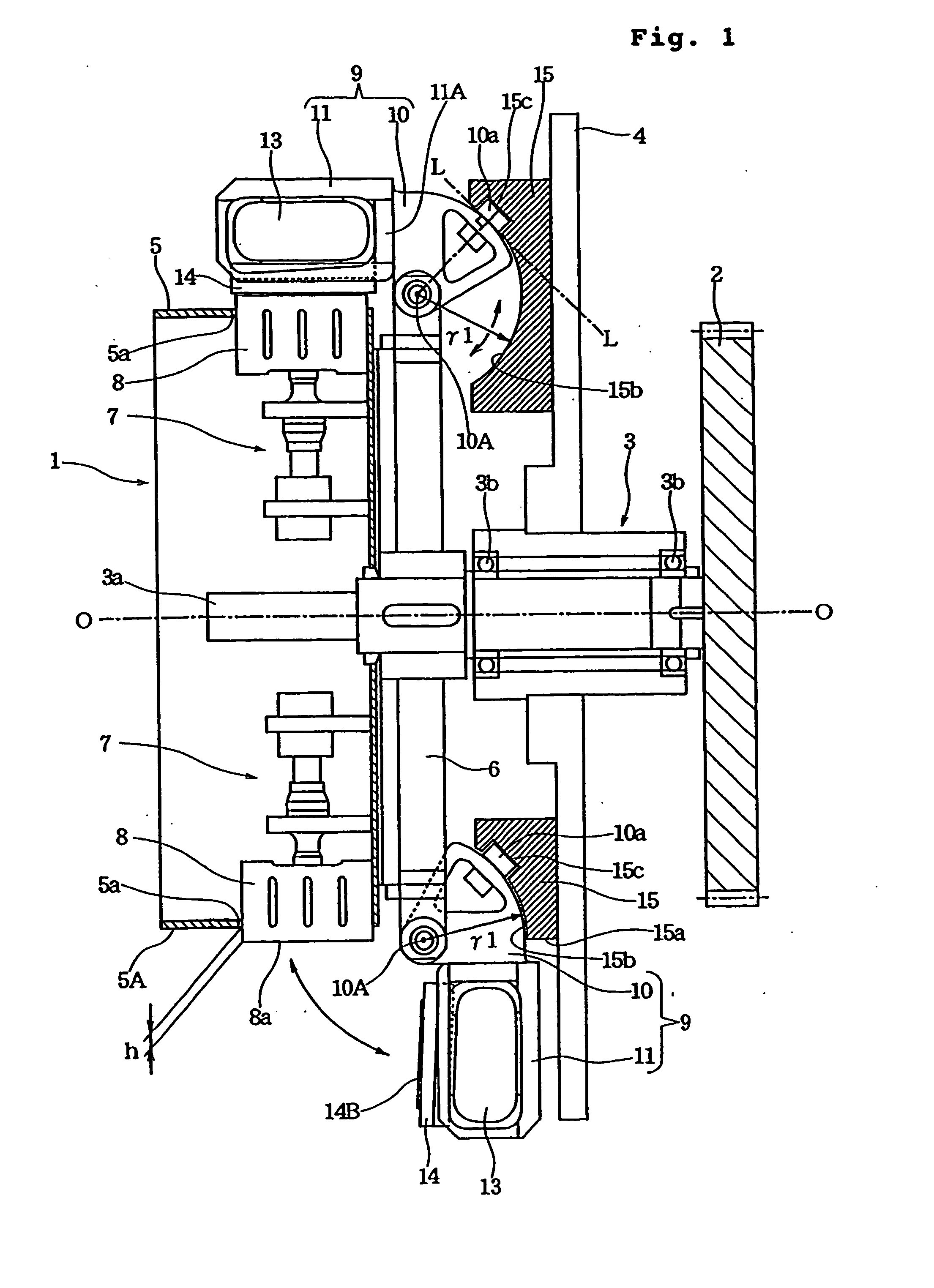
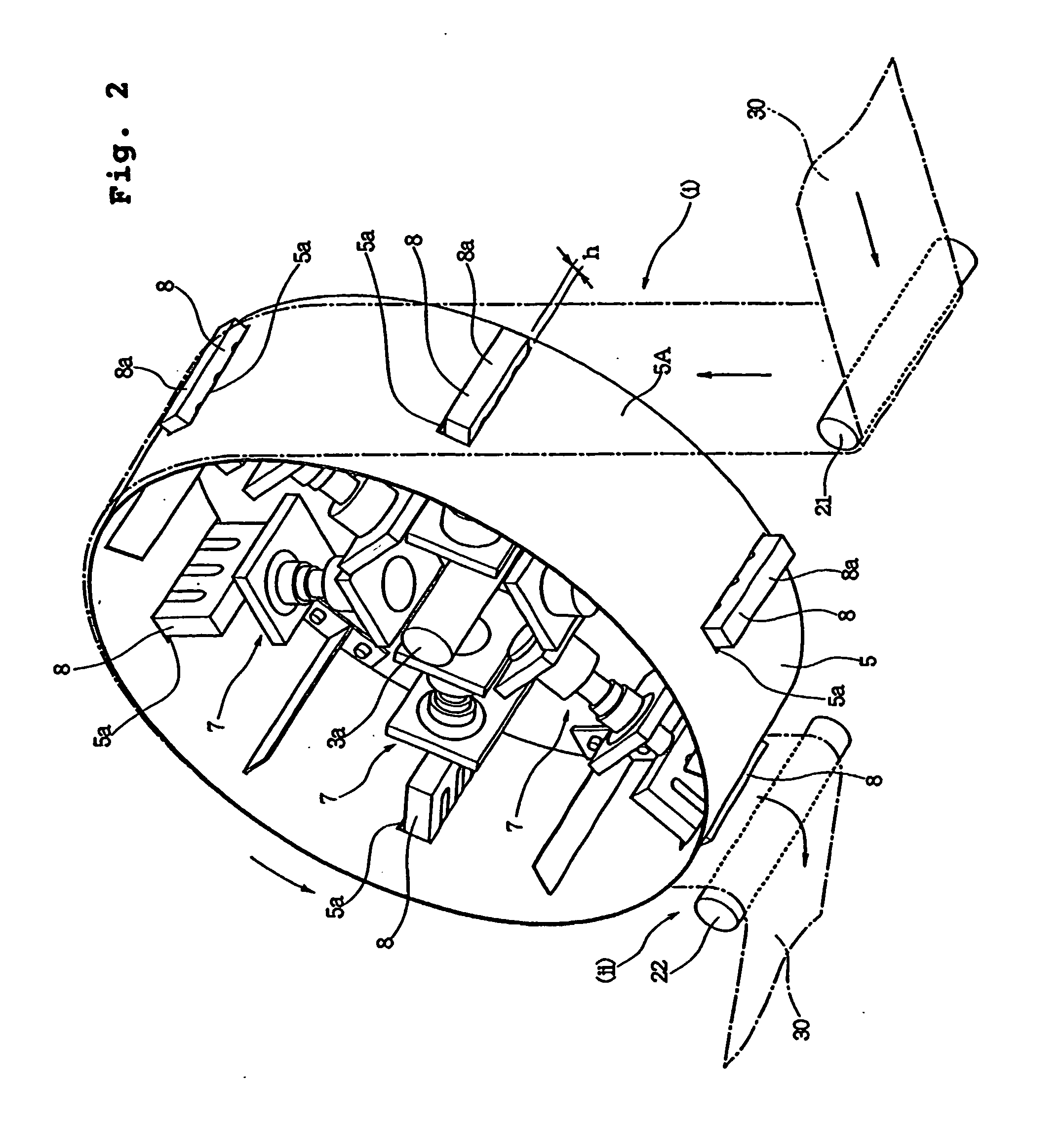
[0070] FIG. 1 is a vertical section of a sealing apparatus according to the present invention as taken along line I-I of FIG. 3, FIG. 2 is a perspective view for explaining a rotating portion of the sealing apparatus, FIG. 3 is an explanatory illustration showing operating condition of the sealing apparatus, FIG. 4 is an exploded perspective view showing a structure of a rocking support member, FIG. 5 is a front elevation showing a shape of a cam member on the side of a stationary portion, FIG. 6 is a side elevation showing a condition where an anvil (second clamping member) is moved at a retracted position away from a horn (first clamping member), FIG. 7A is a side elevation showing a condition where the rocking support member is pivoted to contact the anvil to the horn, and FIG. 7B is a side elevation showing a condition where the anvil is urged onto the horn under pressure with compressing an elastic member.

[0071] In a sealing apparatus 1 shown in FIG. 1, a bearing portion 3 is p...

second embodiment

[0136] As the rocking driving means for driving the rocking support member 9, a cylinder mechanism or the like or a link mechanism which will be discussed later in discussion for the second embodiment may also be employed.

[0137] On the other hand, the elastic member 13 for biasing the anvil may be a coil spring or the like in place of the elastic member discussed above.

[0138] FIGS. 11 to 14 show a sealing apparatus 40 according to a second embodiment of the present invention. FIG. 11 is a vertical section of the sealing apparatus 40, FIG. 12 is a front elevation showing a structure of a cam member, FIG. 13 is a side elevation showing a supporting condition of the anvil 14, and FIG. 14 is an illustration showing a construction of a piping for setting internal pressure of elastic members.

[0139] The sealing apparatus 40 shown in FIG. 11 is different from the sealing apparatus 1 of the first embodiment only in constructions of the rocking driving means and the ultrasonic generating mean...


PUM

PropertyMeasurementUnit
Angleaaaaaaaaaa
Thicknessaaaaaaaaaa
Forceaaaaaaaaaa

Abstract

Disclosed is a sealing apparatus wherein, as a drum (5) and a rotary base (6) are rotated together, a follower (10a) of a rocking support member (9) rockably provided on the outer periphery of the rotary base (6) is guided along a cam groove (15c) of a cam member (15) to drive the rocking support member (9) to rock. When the rotary drum (5) reaches a predetermined rotational position, an anvil (14) supported by the rocking support member (9) is urged onto a horn (8), and then, when it reaches another rotational position, the anvil (14) is moved away from the horn (8). Since the anvil (14) is driven by the rocking motion of the rocking support member (9), entire operation becomes quite simple, and a continuous soft work can be certainly clamped between the horn (8) and the anvil (14).

Description

[0001] The present invention relates generally to a sealing apparatus for forming sealed portion in a continuous soft work for forming soft article, such as disposable diaper, sanitary napkin and so forth, and a manufacturing process of such soft article having sealed portion. More particularly, the invention relates to a sealing apparatus and a manufacturing process, which can certainly perform sealing operation with simple operation.PRIOR ART[0002] For example, Japanese Patent Application Laid-Open No. 10-513128 (PCT / US96 / 00618) discloses an apparatus for manufacturing soft article such as diaper, as non-individual body, by providing ultrasonic seal to a continuous web at regular intervals.[0003] In the above-identified publication, an ultrasonic sealing mechanism constituted of a plurality of ultrasonic horns and anvils is provided in a rotary working drum for rotation together with the rotary working drum. The web is wrapped around the outer peripheral face of the rotary working...

Claims


Application Information

Patent Timeline
IPC IPC(8): A61F13/15B29C65/00B29C65/08
CPCA61F13/15739B29C66/954B29C65/745B29C65/7885B29C66/1122B29C66/21B29C66/346B29C66/73115B29C66/80B29C66/81611B29C66/8163B29C66/82263B29C66/82421B29C66/83511B29C66/83517B29C66/90B29C66/9241B29C2793/00B29K2105/0854B29L2031/4878B29C65/74B29C66/7294B29C66/961B29C66/93431B29C66/93451B29C66/8221B29C66/4312B29C65/7894B29C66/8145B29C66/81465B29C65/08B29C66/81427B29C66/9221B29C66/81463B29C65/087B29C65/00B29C66/934B29C66/431B29C66/73921B29C66/232B29C66/72343B29C66/433B29C66/73182B29C66/73187B29C2793/009B29C66/81469B29C66/81455B29C66/92451B29C66/872B29C66/8324
Inventor NINOMIYA, AKIHIDENOMURA, HIRONORISHINOHARA, JUNJIYAMAMOTO, HIROKI
Owner UNI CHARM CORP
Why Eureka
Try Eureka