Diaphragm, speaker unit using same, headphone and earphone, and diaphragm manufacturing method

a diaphragm and speaker technology, applied in the direction of diaphragm construction, transducer diaphragms, electromechanical transducers, etc., can solve the problems of increasing the probability of increasing the even-order distortion of a sound wave emitted from affecting the displacement symmetry, and affecting the sound quality of the electrodynamic speaker unit. achieve excellent reproduction and improve the effect of displacement symmetry

Active Publication Date: 2020-10-13
ONKYO KK
View PDF29 Cites 0 Cited by
  • Summary
  • Abstract
  • Description
  • Claims
  • Application Information

AI Technical Summary

Benefits of technology

[0022]Thus, regarding shaping processing for the lead line of the voice coil, the first adhesive for fixing the lead line forms the first adhesive layer not reaching three or more recessed ribs, and the second adhesive for further fixing the lead line is applied to the outer peripheral edge portion of the diaphragm on the outermost peripheral side to form the second adhesive layer. Thus, a difference in strength and stiffness of the diaphragm in a circumferential direction is less caused. As a result, the electrodynamic speaker unit using the diaphragm can improve vertical displacement symmetry and linearity of the edge portion of the diaphragm, can reduce rolling of the diaphragm or occurrence of noise, and can provide excellent reproduced sound quality.
[0024]The headphone and the speaker unit can be provided, which in the diaphragm of the electrodynamic speaker unit used for the headphone or the earphone according to the present invention, specifically the diaphragm configured such that the dome portion and the edge portion are integrally formed, improve the displacement symmetry and the linearity regarding the shaping processing for the lead line of the voice coil, prevent failure such as rolling of the diaphragm or occurrence of noise, and provide excellent reproduced sound quality.

Problems solved by technology

Moreover, as also described in JP-UM-A-62-139191, when the diaphragm vibrates vertically, if mobility of the edge portion is different between an upward direction and a downward direction, i.e., displacement symmetry of the edge portion varies, and therefore linearity of the diaphragm is degraded, failure such as rolling of the diaphragm or occurrence of noise is easily caused.
With a difference in the displacement symmetry of the edge portion, there is a problem that the probability of increasing even-order distortion of a sound wave emitted from the electrodynamic speaker unit is increased and reproduced sound quality is degraded.
In the electrodynamic speaker unit using the diaphragm as described above, the voice coil is attached to the diaphragm, and therefore, shaping processing for a lead line configured to supply audio signal current to the voice coil becomes a challenge.
The shaping processing for the lead line may include processing using aerial wiring not fixing the lead line to the diaphragm for the purpose of reducing a vibration system weight, but failure such as disconnection or a jumping-rope phenomenon is easily caused.
For this reason, there is a difference in strength and stiffness between a portion where the adhesive for fixing the lead line of the voice coil is applied and cured and a portion where no adhesive is applied, leading to a problem that deformation of the diaphragm is easily caused.
Moreover, the electrodynamic speaker unit using the diaphragm has a problem that rolling of the diaphragm is easily caused and vertical symmetry is easily degraded.

Method used


Image

  • Diaphragm, speaker unit using same, headphone and earphone, and diaphragm manufacturing method
  • Diaphragm, speaker unit using same, headphone and earphone, and diaphragm manufacturing method
  • Diaphragm, speaker unit using same, headphone and earphone, and diaphragm manufacturing method

Examples


first embodiment

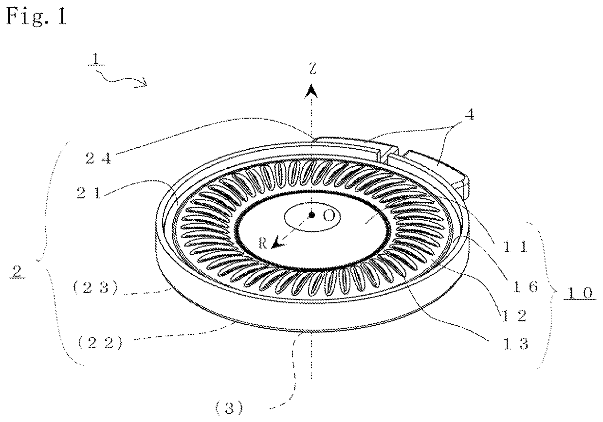
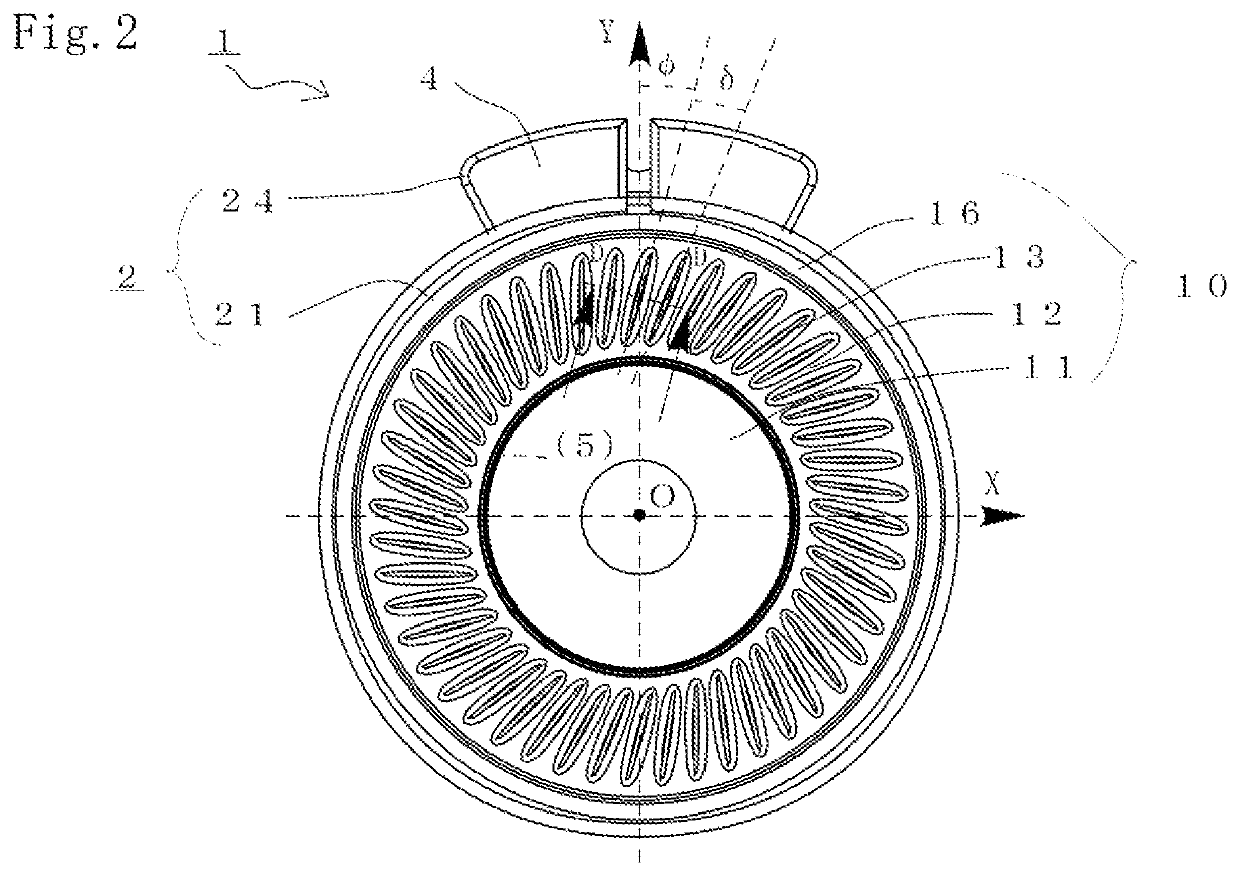
[0033]FIGS. 1 and 2 are views for describing an electrodynamic speaker unit 1 used for a headphone or an earphone according to a preferred embodiment of the present invention. Specifically, FIG. 1 is a perspective view of an outer appearance of the speaker unit 1 from a front side, and FIG. 2 is a view of the speaker unit 1 from the front side. Note that the form of the speaker unit 1 is not limited to that in the case of the present embodiment. Moreover, a configuration of the speaker unit 1 unnecessary for description of the present invention will not be shown in the figures, and will not be described.

[0034]The speaker unit 1 of the present embodiment is an electrodynamic speaker used for the headphone or the earphone arranged in the vicinity of an ear of a user and having a small nominal diameter of 40 mm. Note that the speaker unit 1 is attached to a cavity of the headphone or a body of the earphone to form the headphone or the earphone. Note that a specific form of the headphon...


PUM


Abstract

An edge portion of a diaphragm is configured such that multiple recessed ribs formed by recessing of a raised surface are provided in an inclination direction inclined with respect to a radial line passing through a center point and are arranged rotationally symmetrically, and among the recessed ribs and a fixing portion defined on the outermost peripheral side of the diaphragm, defines an outer peripheral edge portion at which no recessed ribs are formed. A voice coil is coupled to a voice coil attachment portion. A lead line is fixed with a first adhesive forming a first adhesive layer along a valley portion defined between a certain recessed rib and an adjacent recessed rib thereof on a back side of the edge portion, and is further fixed with a second adhesive forming a second adhesive layer with the lead line being curved along the outer peripheral edge portion.

Description

BACKGROUND OF THE INVENTION1. Field of the Invention[0001]The present invention relates to a diaphragm of an electrodynamic speaker unit used for a headphone or an earphone attached to an ear of a user to reproduce audio.2. Description of the Related Art[0002]In a compact electrodynamic speaker unit used for a headphone or an earphone, a diaphragm is used in some cases, the diaphragm being formed from a film-shaped member formed using a resin material such as polyethylene terephthalate (PET) or polyetherimide (PEI) and being configured such that a dome portion and an edge portion extending at the outer periphery of the dome portion are integrated. In this electrodynamic speaker, a voice coil configured to supply audio signal current is, from a back side, attached to a joint portion between the center dome portion and the edge portion integrally formed in the diaphragm. An outer peripheral end side of the edge portion of the diaphragm is fixed to a frame coupled to a compact lightwei...

Claims


Application Information

Patent Timeline
Patent Type & Authority Patents(United States)
IPC IPC(8): H04R9/06H04R7/14H04R1/10H04R7/18H04R9/02H04R7/12H04R25/00H04R1/20H04R9/04H04R31/00
CPCH04R7/18H04R31/003H04R7/127H04R9/025H04R1/10H04R9/06H04R25/00H04R7/12H04R9/04H04R1/20H04R7/14H04R7/20
Inventor FUJITANI, TAKESHI
Owner ONKYO KK
Why Eureka
Try Eureka