
Eureka
For R&D, Eureka makes reading and utilizing patents & technical documents easy.
Eureka AIR
Designed for self-driven R&D workflows. Generate viable solutions, solve complex R&D challenges, empower your innovation with AI.

Eureka Materials
Designed for material experts only. Revolutionize your material R&D, from search, analyze, to developing new materials.

TechResearch
Generate reliable direction feasibility study reports for your R&D in just a few steps.

TechSeek
Discover and master advanced knowledge NOW. Basics, ideas, possibilities, all at once.

TechMind
As an expert in R&D Theories, TechMind can generates customized viable solutions instantly.

TechRisk
Analyze your overall solution with one click, know your potential R&D risks in advance.

TechMonitor
Get weekly tech updates, stay abreast of the latest tech innovations and key insights.
Exhaust purification apparatus and utilization thereof
- Summary
- Abstract
- Description
- Claims
- Application Information
AI Technical Summary
Benefits of technology
Problems solved by technology
Method used
Image

Examples
first embodiment
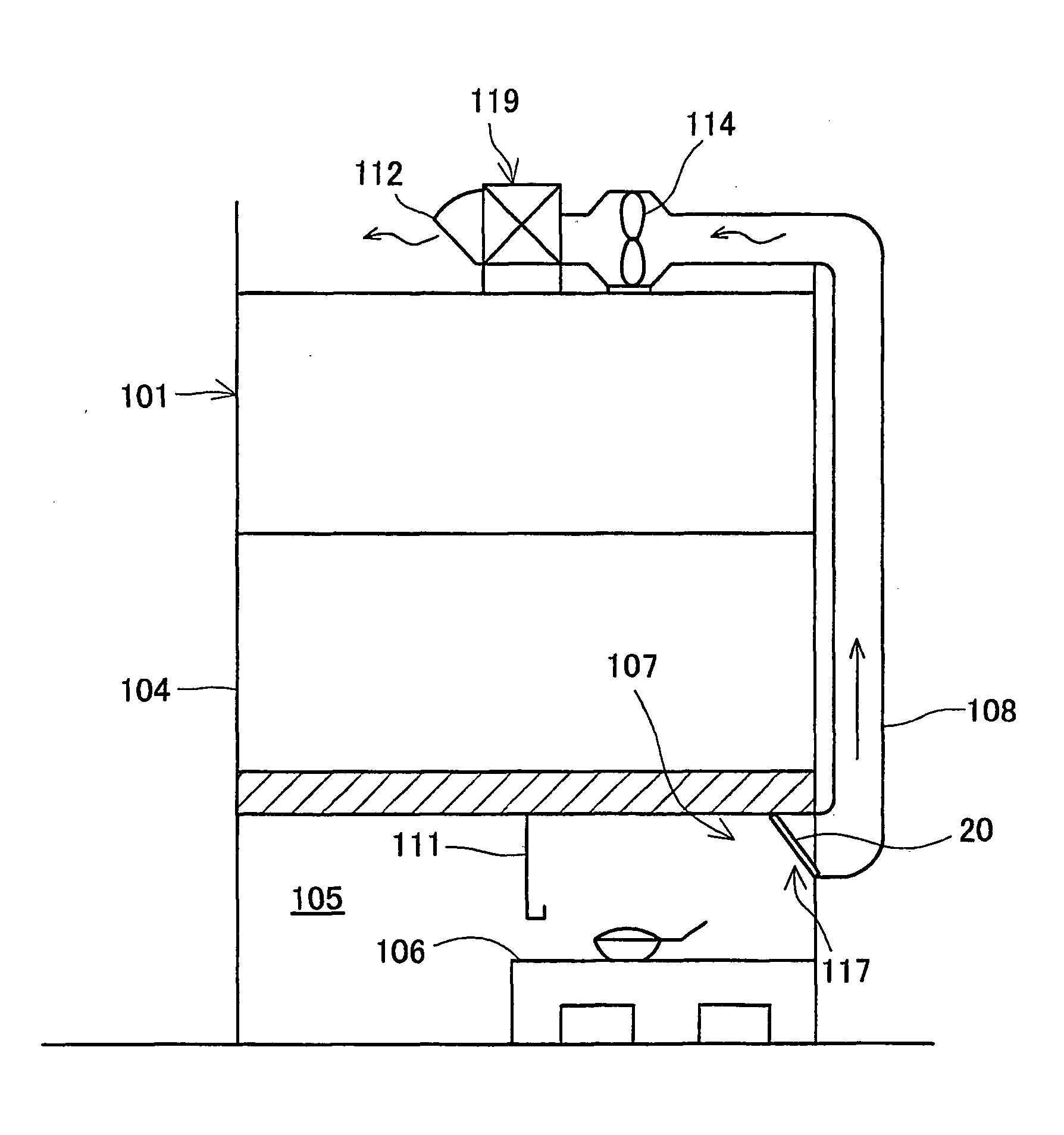
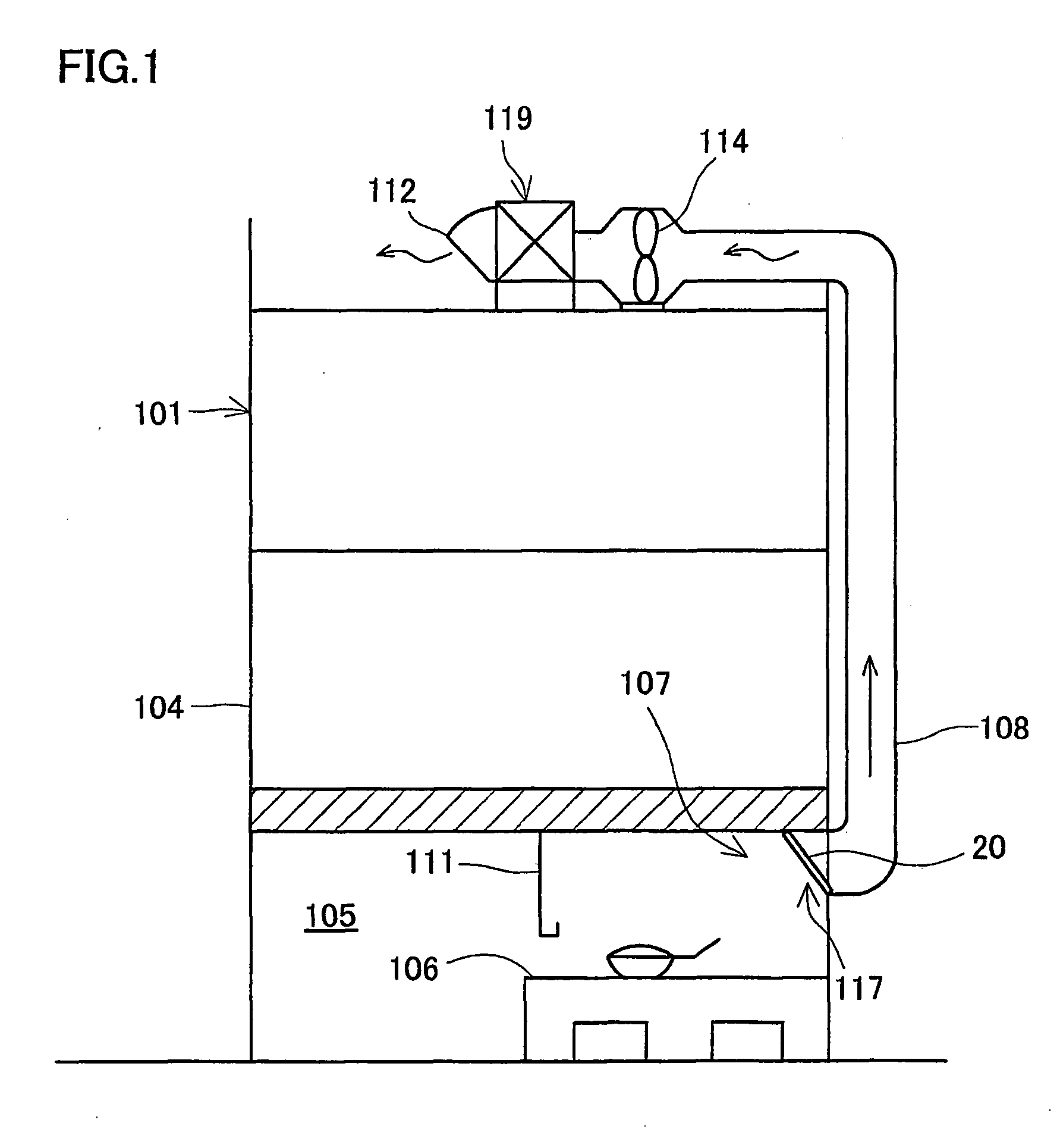
[0063] The First Embodiment relates to the installation of the exhaust purification apparatus in accordance with the present invention in an exhaust duct leading from a kitchen to the outside.
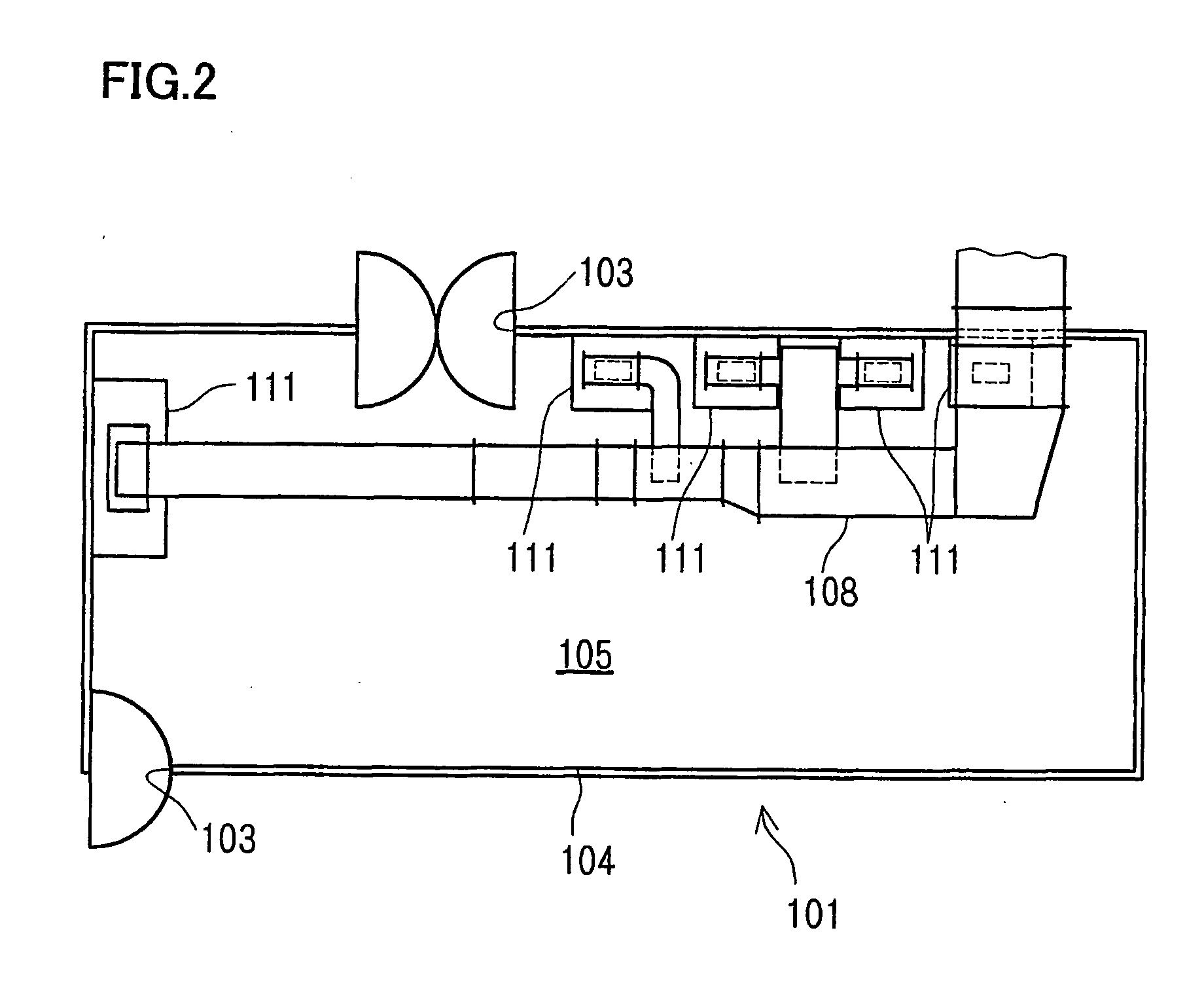
[0064] As shown in FIG. 1 and FIG. 2, a kitchen 105 is partitioned by a structural wall 104 of a building 101. A door way 103 is formed in the structural wall 104. A plurality (for example, five) cooking stands 106 are disposed in the kitchen 105. A range hood 111 is mounted above each cooking stand 106. One end of an exhaust duct 108 extending to the rooftop exhaust release opening 112 along the outer wall surface of the building 101 is opened in the range hood 111.
[0065] The exhaust purification apparatus 107 can be said to be generally composed of a pretreatment section 117 provided in connection to one end of the exhaust duct 108, and an optical treatment section 119 provided in the vicinity of the other end inside the exhaust duct 108. A fan 114 is provided between the pretreatment section...
third embodiment
[0138] The photocatalytic unit 61 is disposed so as to cover the exhaust release opening 312 formed in the side surface of the cooking device body 301, and the photocatalytic filter 62 faces the exhaust release opening 312. The exhaust path where the photocatalytic unit 61 is disposed is in the lower portion inside the cooking device body 301. Therefore, a large space can be easily provided. The exhaust sucked in herein is released, so as to be dispersed by the fan 307 to all four sides inside the cooking device body 301. As a result, the flow velocity of the exhaust can be further decreased and odorous components, present in the exhaust, can be efficiently removed by the photocatalytic filter 62, similar to the
[0139]
fourth embodiment
[0140] The present embodiment relates to a cooking system having connected therein a plurality of cooking devices equipped with the exhaust purification apparatus in accordance with the present invention. A cooking device used in this embodiment is shown in FIG. 16. This cooking device has a configuration similar to that of the cooking device of the Fourth Embodiment; the difference between the two is described below.
[0141] The de-oiling filter 20 is disposed below the outer box 309. The dust collector 50 and the photocatalytic unit 61 are disposed one above the other at the side of the de-oiling filter. Exhaust generated from the cooking unit flows from the side surface of the inner box 308 along the lower surface toward the de-oiling filter 20 located below the inner box 308. The exhaust path in this portion is formed so as to become narrower toward the de-oiling filter 20, thereby increasing the flow velocity of the exhaust. In the present embodiment, the photocatalytic units 61 ...
PUM
| Property | Measurement | Unit |
|---|---|---|
| Fraction | aaaaa | aaaaa |
| Fraction | aaaaa | aaaaa |
| Linear density | aaaaa | aaaaa |
Abstract
Description
Claims
Application Information
 - R&D Engineer
- R&D Manager
- IP Professional
- Industry Leading Data Capabilities
- Powerful AI technology
- Patent DNA Extraction
Browse by: Latest US Patents, China's latest patents, Technical Efficacy Thesaurus, Application Domain, Technology Topic, Popular Technical Reports.
© 2024 PatSnap. All rights reserved.Legal|Privacy policy|Modern Slavery Act Transparency Statement|Sitemap|About US| Contact US: help@patsnap.com