Filling valve

a filling valve and valve body technology, applied in the direction of liquid handling, filling without pressure, packaging goods, etc., can solve the problems of sanitary problems, the vent tube which defines the exhaust passage or the spreader must be changed, etc., and achieve the effect of stable filling operation and excellent sanitary performan

Active Publication Date: 2004-06-24
SHIBUYA IND CO LTD
View PDF4 Cites 5 Cited by
  • Summary
  • Abstract
  • Description
  • Claims
  • Application Information

AI Technical Summary

Benefits of technology

0010] The present invention has been made in order to overcome the described problems and has for its object the provision of a filling valve which is excellent in sanitary performance and which avoids the need of replacement of an attachment for vessels of differing sizes and shapes. It is also an object of the present invention to provide a filling valve which allows a filling operation to take place through the center of a vessel and which allows a stable filling operation which is not influenced by the shape of the vessel.

Problems solved by technology

In addition, the liquid to be filled contacts the vent tube during the filling operation, thus leaving a sanitary problem.
Furthermore, when the size or the shape of the vessel is changed, the vent tube which defines the exhaust passage or the spreader must be changed, which is a disadvantage.

Method used


Image

  • Filling valve
  • Filling valve
  • Filling valve

Examples


Embodiment Construction

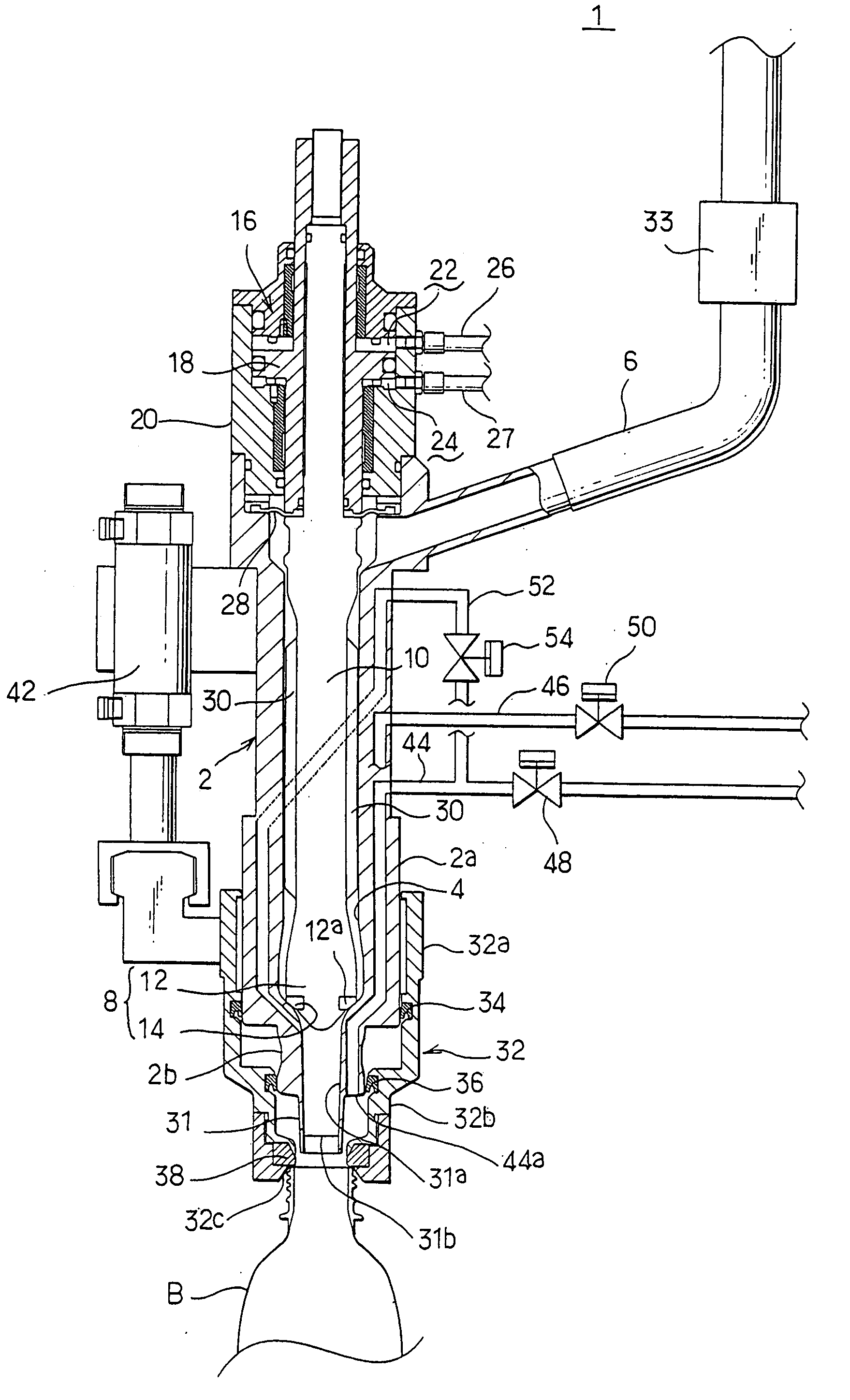
[0020] The present invention will now be more specifically described with reference to an embodiment thereof shown in the drawings. The filling valve, generally designated by numeral 1, is installed on a filler of a so-called lifterless type which is not provided with a mechanism for elevating a vessel B. The vessel B is conveyed in a horizontal plane to the filling valve 1, and subsequently, a vessel opening packing which will be described later is caused to descend to be pressed against the mouth of the vessel B to seal it, whereupon a filling operation of the vessel B takes place by the filling valve 1.

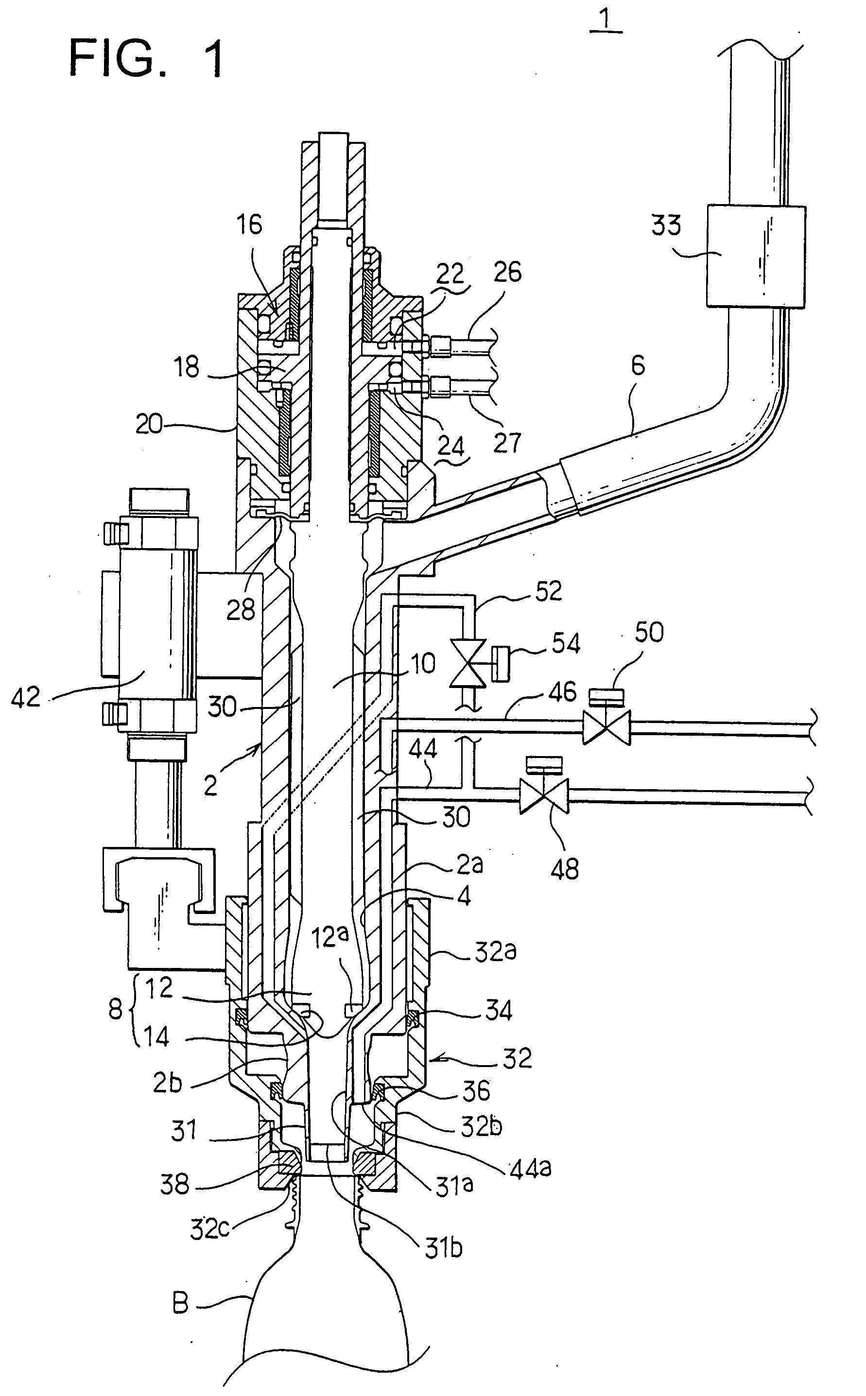
[0021] The filling valve 1 includes a valve housing 2, which is formed with a portion 2a of an increased diameter toward its bottom, and is also formed with a portion 2b of a reduced diameter which is located below the portion 2a of an increased diameter. A liquid to be filled which is fed from a fluid liquid tank, not shown, through a liquid supply piping 6 for filling, is passed ...


PUM

PropertyMeasurementUnit
diameteraaaaaaaaaa
perimeteraaaaaaaaaa
pressureaaaaaaaaaa

Abstract

A liquid passage 4 for filling which communicates with a liquid supply piping 6 for filling is formed within a valve housing 2 and carries a filling nozzle 31 at its lower end. The liquid passage 4 is opened or closed by a liquid valve. A packing 38 which seals the mouth of a vessel B, a cylinder 42 which elevates the packing 38, a flow meter 33 which detects a filled content of the liquid which is filled into the vessel B, and an exhaust passage 44 formed in the valve housing 2 are provided. The exhaust passage 44 has an opening disposed toward the vessel which is disposed outside an opening of the filling nozzle 31, and the opening of the filling nozzle 31 is maintained above the elevation of the liquid level which is filled into the vessel B during the filling operation. The filling valve assures a sanitary excellence and is usable with vessels B of differing sizes and shapes.

Description

BACKGROUND OF THE INVENTION AND RELATED ART STATEMENT[0001] The present invention relates to a filling valve installed on a filler, and in particular, to a filling valve which is used to fill a carbonated beverage or non-carbonated beverage into a vessel while the mouth of the vessel is sealed by a seal member such as a packing.[0002] A filler generally includes a filling valve comprising a liquid passage for filling formed within a valve housing, a filling nozzle mounted on the downstream end of the liquid passage and a liquid valve which functions to open or close the passage through which the liquid passes, the arrangement being such that the filled liquid is injected into the vessel from the filling nozzle mounted on the downstream end of the liquid passage while the liquid valve is open.[0003] When such a filler is used to fill a vessel with a carbonated beverage, for example, there is a need to close a top end opening of the vessel, and accordingly, a cylindrical elevating mem...

Claims


Application Information

Patent Timeline
Patent Type & Authority Applications(United States)
IPC IPC(8): B67C3/04B67C3/28
CPCB67C3/281B67C3/04B67C3/06
Inventor TSUKANO, KENICHITANIKAWA, KATSUNORIKITAYAMA, TARO
Owner SHIBUYA IND CO LTD
Why Eureka
Try Eureka