Electrical conduit

a technology of electric conduits and conduits, applied in the direction of electrical cable installations, bus-bar installations, electrical apparatus, etc., can solve the problems of less efficient heat exchange with the outside, and achieve the effect of improving the form factor of these conductors, improving the shape of the cross-section of conductors, and increasing the distance between each conductor

Inactive Publication Date: 2004-06-24
SCHNEIDER ELECTRIC IND SAS
View PDF2 Cites 9 Cited by
  • Summary
  • Abstract
  • Description
  • Claims
  • Application Information

AI Technical Summary

Benefits of technology

[0006] The object of the invention is to modify the shape of the cross-section of the conductors to improve the form factor of these conductors with the enclosure and therefore the heat exchange between conductors and enclosure without penalising the overall size of the busbar (i.e. without increasing the distance between each conductor for example) and without increasing the cross-section of the conductors of the busbar, so as to be able to keep the same cabinets and the same enclosures.

Problems solved by technology

This second technology increases the reactance of the electrical busbar and makes the heat exchange with the outside less efficient, however it does enable junction boxes to be fitted and removed much more easily by means of a plug-in type connection.

Method used


Image

  • Electrical conduit
  • Electrical conduit

Examples


Embodiment Construction

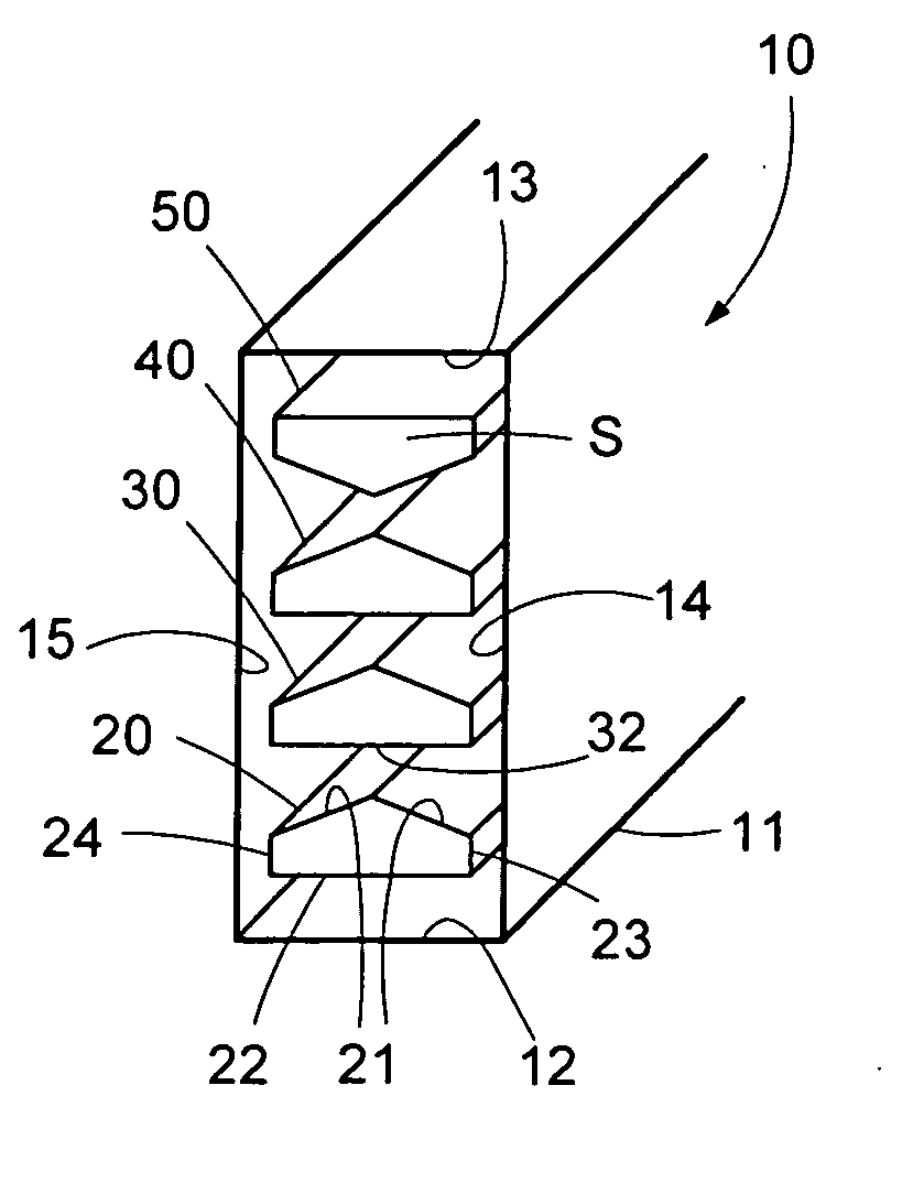
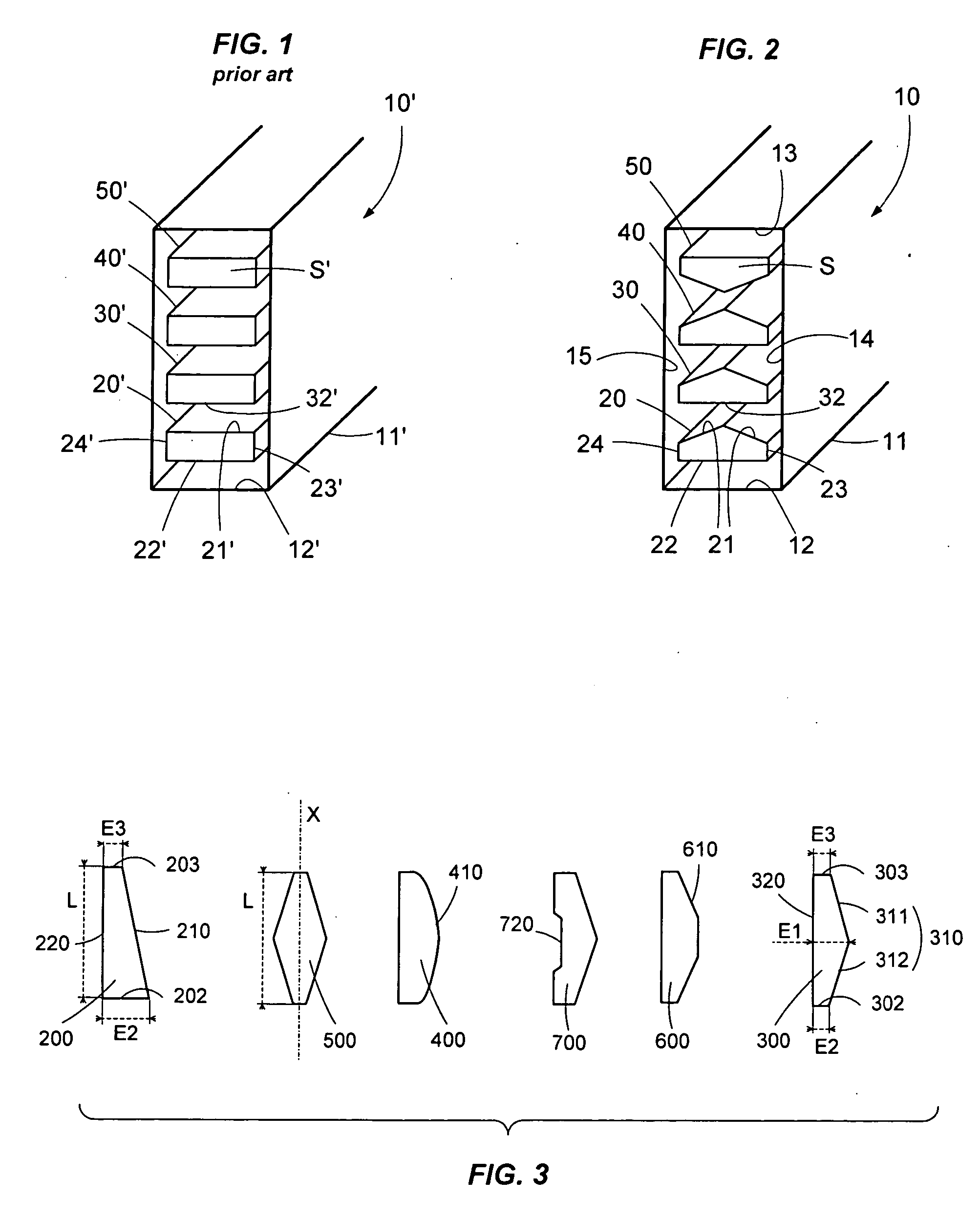
[0017] FIG. 1 represents a pre-fabricated electrical busbar 10' according to the prior art comprising four conducting bars 20',30',40',50' in a closed metal enclosure 11' of substantially rectangular straight cross-section. The four conducting bars are rigid, parallel, spaced out from one another and separated from the enclosure 11'. Usually, the straight transverse section S' (hereinafter called the cross-section) of all these conducting bars is substantially rectangular and comprises, for example for the bar 20', two straight and parallel, opposite main faces 21',22', situated between two opposite short faces 23',24', straight and perpendicular to the main faces. The rectangular shape of the cross-sections of the bars in such a busbar 10' does not always enable an efficient heat exchange to be achieved between the conducting bars and the metal enclosure 11' for the heat radiated by the bars when an electric current is flowing through the latter.

[0018] It is generally assumed that ...


PUM


Abstract

The invention relates to an electrical busbar for transportation and distribution of electrical power comprising several parallel, metal conducting bars spaced out from one another inside a metal enclosure, each conducting bar having a cross-section of elongate shape. At least one conducting bar is provided with a thickness near to the centre of the cross-section of said conducting bar that is greater than thickness of at least one of the ends of the cross-section of said conducting bar.

Description

[0001] The present invention relates to an electrical busbar for transportation and distribution of electrical power composed of several, rigid, parallel, metal electrical conductors, spaced out from one another inside a metal enclosure, the shape of the conductors whereof enables the heat exchanges with the external environment through the metal enclosure to be optimized.STATE OF THE ART[0002] Electrical power transportation / transmission and distribution systems via prefabricated electrical busbars or canalizations are well known. They serve the purpose on the one hand of transporting power from one point to another in an electrical installation, for example from one electrical switchboard to another electrical switchboard, and on the other hand of distributing this electrical power for the different receivers located along the busbar, proposing fixed, regularly spaced apart connection points. The receivers are then supplied by means of junction boxes connected to these connection ...

Claims


Application Information

Patent Timeline
Patent Type & Authority Applications(United States)
IPC IPC(8): H02G5/06
CPCH02G5/06
Inventor PIERROT, HENRIDUPOUX, CHRISTIANBACHA, ZINE
Owner SCHNEIDER ELECTRIC IND SAS
Why Eureka
Try Eureka