Mixer water faucet

a technology of water faucet and mixer, which is applied in the direction of multiple way valves, mechanical devices, transportation and packaging, etc., can solve the problems of reducing the convenience of users, increasing the form factor, and reducing utilization, so as to achieve smoother holding

Active Publication Date: 2019-05-16
HAMAT SANITARY FITTINGS & CASTING LTD
View PDF0 Cites 6 Cited by
  • Summary
  • Abstract
  • Description
  • Claims
  • Application Information

AI Technical Summary

Benefits of technology

[0031]In some embodiments, optionally, the entirety of the auxiliary spout or spraying-unit 26 may be a generally flat unit, or a rectangular unit, or a box or cuboid or rectangular cuboid unit; and may not comprise any L-shaped ending or edge or protrusion or spout-area; thereby keeping the form-factor of the unit small, and / or thereby allowing smoother holding by the user which may hold the unit similar to holding a flat handle and without an L-shaped ending or protrusion, and / or thereby enabling the auxiliary spout or spraying-unit 26 to spray water in an un-obstructed manner from a flat or generally-flat water outlet of the auxiliary spout 26 and without being restricted or obstructed by a protrusion or an L-shaped ending of the spout. In other embodiments, the spraying unit or the auxiliary spout element 26 may be generally flat but may also have a slightly protruding water-outlet at or near its distal end (e.g., away from the base of the faucet), through which the water flows out or is sprayed out or is spouted out.

Problems solved by technology

Applicants have realized that this configuration may suffer from one or more problems or disadvantages, for example: (a) the need to drill two separate holes in a surface or platform (e.g., granite, marble, artificial marble, or other kitchen platform or surface); (b) increased form-factor, and reduced utilization of the kitchen platform due to the fact that two separate units occupy space, side-by-side or next to each other; (c) the need to maintain, clean and / or repair two separate units; (d) reduced convenience for some users, who need to reach sideways to grasp the side-spray unit, while the user is standing in proximity to (or in front of) the main water faucet.

Method used


Image

  • Mixer water faucet
  • Mixer water faucet
  • Mixer water faucet

Examples


Embodiment Construction

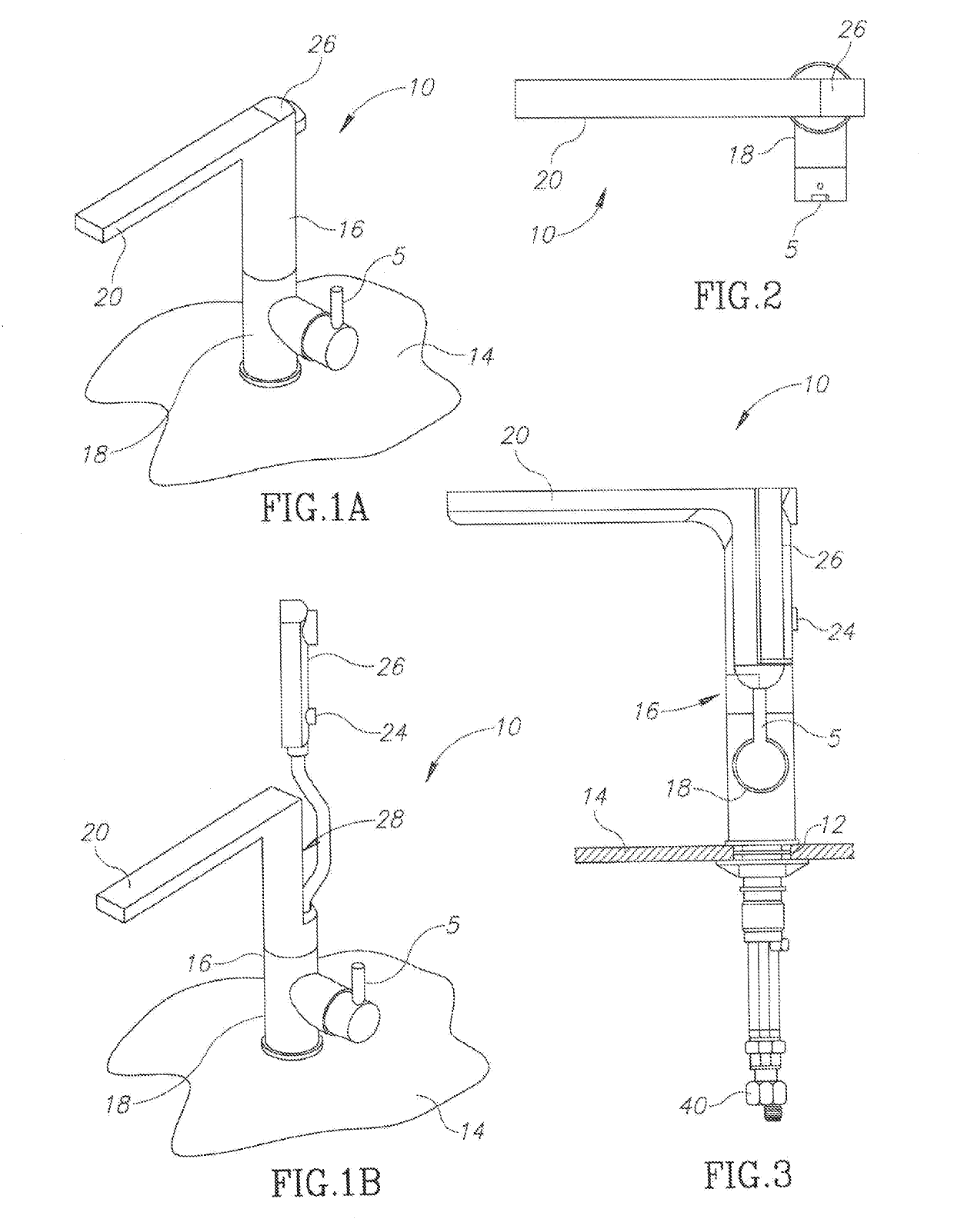
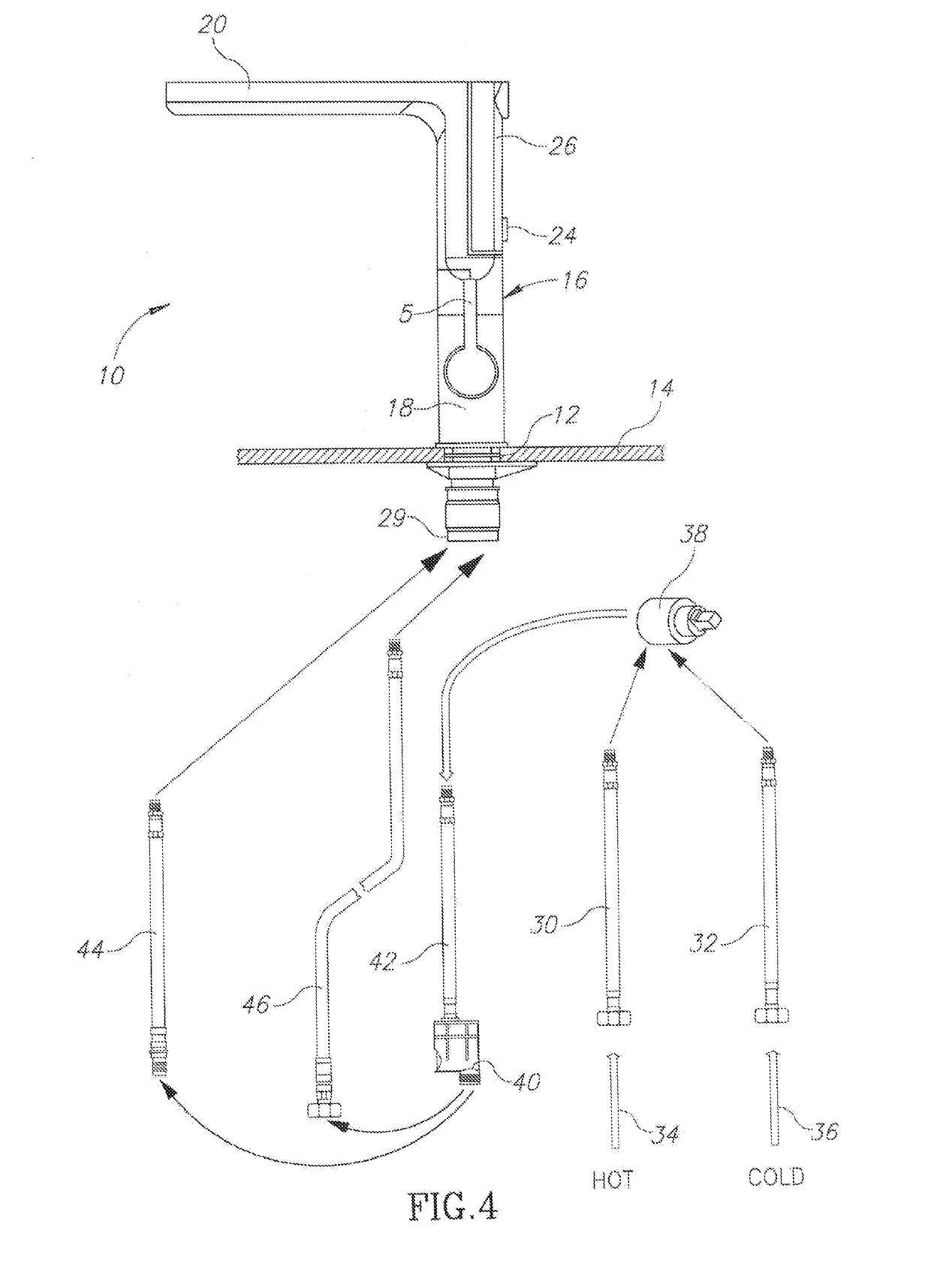
[0046]Referring now to FIGS. 1-3, there is seen a water faucet, referenced generally 10, generally as described above, installed in a single hole 12, formed in a work surface or platform 14. Typically, but way of non-limiting example only, hole 12 has a diameter which is typically 35 mm as known in the art. Faucet 10 includes a faucet body 16 which may have an outside diameter of 35-50 mm as known in the art, and is supported on platform 14 via a housing 18 and shank 29. Body 16 is rotatable relative to housing 18 which has a fixed position relative to platform 14, and both are held in position via a suitable system of fasteners as illustrated and as generally known in the art. Faucet body 16 has a main spout 20 to which water is supplied as shown and described herein, inter alia, in conjunction with FIG. 4, by suitable operation of selector handle 5 and mode selector switch 24, mounted onto auxiliary spout 26. Operation of handle 5 and mode selector switch are generally as known in...


PUM


Abstract

A mixer water faucet for installation through a bore in a work surface in proximity to a water supply, includes a stationary housing extending transversely through the bore; a faucet body mounted onto the housing, rotatable relative thereto; a main and auxiliary spouts extending from the housing; main and auxiliary supply hoses extending through the housing for conveying water to the main and auxiliary spouts, respectively; and a diverter for selectably directing a supply of water to the main and auxiliary spouts, wherein the main spout rotates about a rotation axis extending through the faucet body, the rotation causing a lateral movement and partial twisting of the auxiliary water supply hose with respect to the main water supply hose thereby to allow thereby to allow freedom of movement of the auxiliary spout and the auxiliary hose during extension and retraction thereof.

Description

CROSS REFERENCE TO RELATED APPLICATIONS[0001]This is a continuation-in-part of U.S. patent application Ser. No. 15 / 477,091 filed Apr. 2, 2017, which claims the benefit of U.S. Provisional Patent Application No. 62 / 317,645 filed Apr. 4, 2016. The contents of the foregoing patent applications are incorporated by reference herein in their entirety.FIELD OF THE INVENTION[0002]The present invention relates to the field of water faucets and water taps.BACKGROUND[0003]A water faucet or water tap is a device able to control the flow of water. A water faucet may allow a user to commence and to stop the flow of water from a plumbing system or from a water-delivery system. A water faucet may further allow a user to modify the pressure of water flow, or the volume of water that flows per time unit.[0004]Some water faucets may be implemented as a “mixer tap”, for example, featuring a single handle enabling the user to mix hot water supply with cold water supply, to achieve a desired temperature....

Claims


Application Information

Patent Timeline
Patent Type & Authority Applications(United States)
IPC IPC(8): F16K11/087E03C1/04
CPCF16K11/087E03C1/0402E03C1/0404E03C1/0412E03C2001/0415E03C2201/30Y10T137/9464
Inventor PIRUTIN, SHLOMO
Owner HAMAT SANITARY FITTINGS & CASTING LTD
Why Eureka
Try Eureka