Helicopter rotor and method of repairing same

Inactive Publication Date: 2004-06-24
ADVANCED COMPOSITE STRUCTURES LTD
View PDF2 Cites 46 Cited by
  • Summary
  • Abstract
  • Description
  • Claims
  • Application Information

AI Technical Summary

Benefits of technology

0009] Minor impact damage to a polymeric leading edge can readily be repaired in the field rather than dismounting the blade and shipping it away for repair, as would be the case with damage to a conventional leading edge.
0010] According to another aspect of the present invention there is provided a method of protecting the leading edge of an aerofoil from erosion, comprising securing to the leading edg

Problems solved by technology

On the other hand, it is to be noted that when used in the outboard flight section of a helicopter rotor, the high centri

Method used


Image

  • Helicopter rotor and method of repairing same
  • Helicopter rotor and method of repairing same
  • Helicopter rotor and method of repairing same

Examples


Example

EXAMPLE

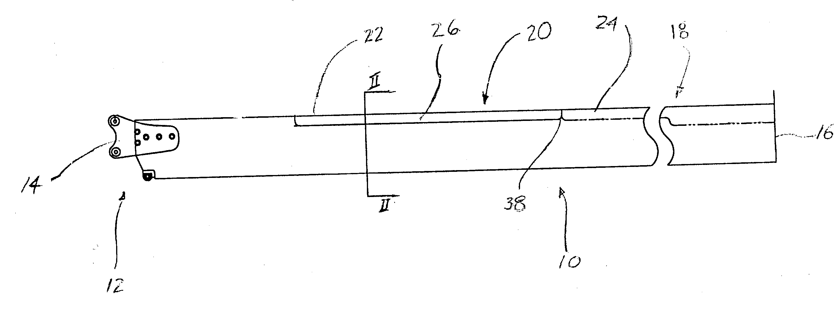
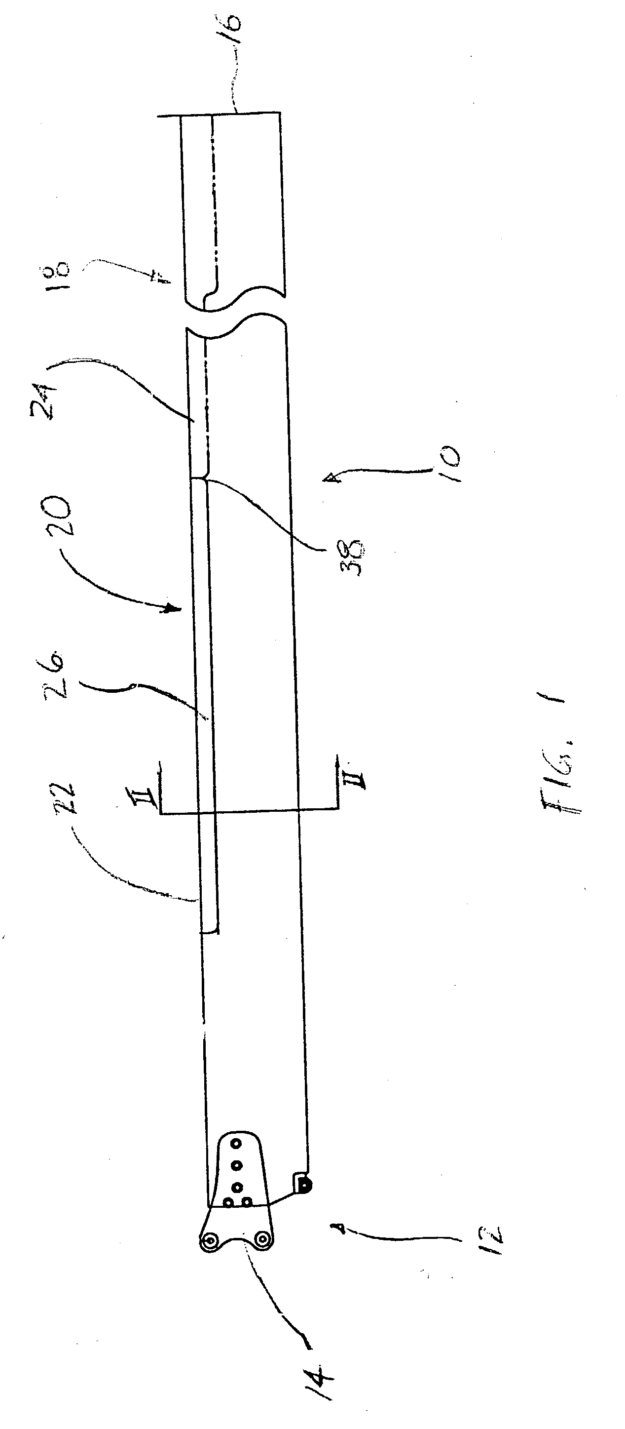
[0022] With the illustrated blade 10, the repair area of the blade is marked off. It is then abraded and cleaned with an appropriate solvent.

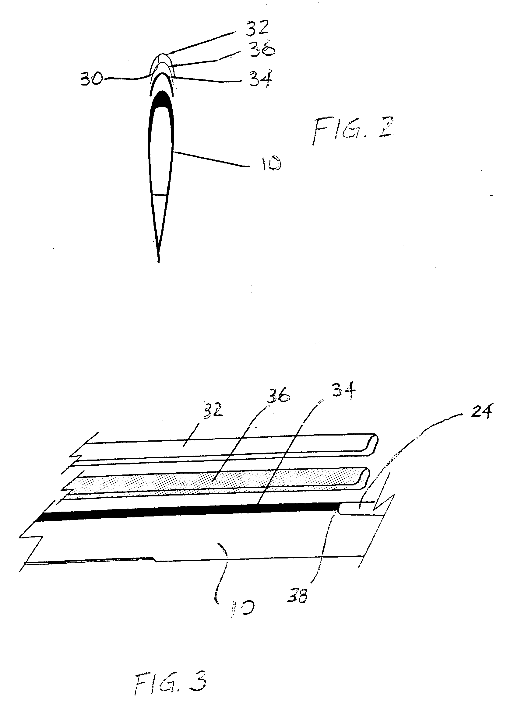
[0023] The bonding surface 30 of a polyurethane strip 32 is also abraded and cleaned with a solvent.

[0024] Adhesive 34 is applied to the abraded bonding surfaces of the blade and the polyurethane strip.

[0025] A scrim cloth 36, in this case 0.008 inch (00.2 mm.)nylon is positioned smoothly over the repair area, leaving no wrinkles or creases.

[0026] The polyurethane strip 32 is then positioned on the repair area over the scrim cloth and subjected to a uniform pressure of 15 psi (10.sup.5 N / m.sup.2) and an elevated temperature (e.g. 180.degree. F. (82.degree. C.) for a duration sufficient to cure the adhesive. It has been found that good conformity to the original shape of the blade and uniform adhesion are achieved through the use of a pressurized bladder acting on the outer surface of the polymeric sheet during curing of the adhesive.

[002...


PUM


Abstract

An aerofoil, particularly a helicopter main rotor blade has a leading edge protector comprising a strip of resilient polymer, preferably polyurethane, adhered to the leading edge of the blade.

Description

FIELD OF THE INVENTION[0001] The present invention relates to aerofoils, and more particularly to the protection of aerofoil leading edges from erosion damage. The invention has particular application to rotary wings, for example helicopter rotor blades.BACKGROUND[0002] The invention was developed in the environment of helicopter rotor blade repair, and will be described primarily in connection with that application. It will be understood by those knowledgeable in the art that the invention may have wider application to aerofoils for other purposes.[0003] The leading edges of helicopter rotor blades are subject to environmental wear, particularly when the helicopter is operated in harsh conditions, for example with significant quantities of ambient sand or salt. It has been found in particular that there is a recurring problem of skin erosion located inboard of the metal leading edge abrasion strips in main rotor blades. Current practice is to remove the blades from the helicopter a...

Claims


Application Information

Patent Timeline
IPC IPC(8): B64C11/20B64C27/473
CPCB64C27/473B64C11/205
Inventor ANNING, BRUCE D.
Owner ADVANCED COMPOSITE STRUCTURES LTD
Why Eureka
Try Eureka