Radio access network and operation control method for the same

Inactive Publication Date: 2004-06-24
NEC CORP
View PDF4 Cites 6 Cited by
  • Summary
  • Abstract
  • Description
  • Claims
  • Application Information

AI Technical Summary

Problems solved by technology

Accordingly, it is difficult to provide a system having both an excellent scalability and flexibility in the conventional RNC.
When, however, a C plane control device is physically separated from a U plane control device in a radio access network, the exchange of control information between protocol entities, which is closed so far inside the RNC, is carried out between various devices, so that t

Method used


Image

  • Radio access network and operation control method for the same
  • Radio access network and operation control method for the same
  • Radio access network and operation control method for the same

Examples


first embodiment

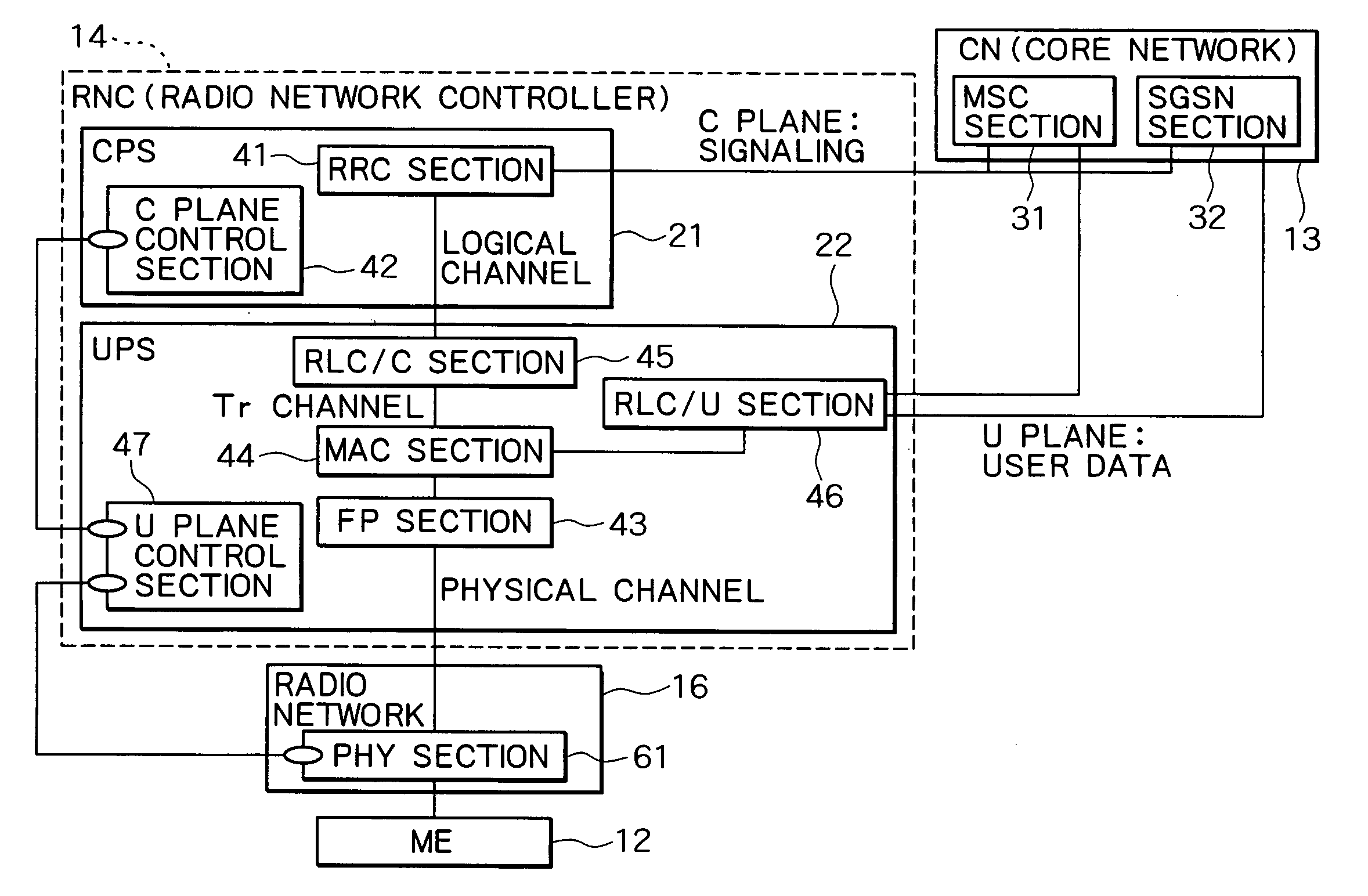
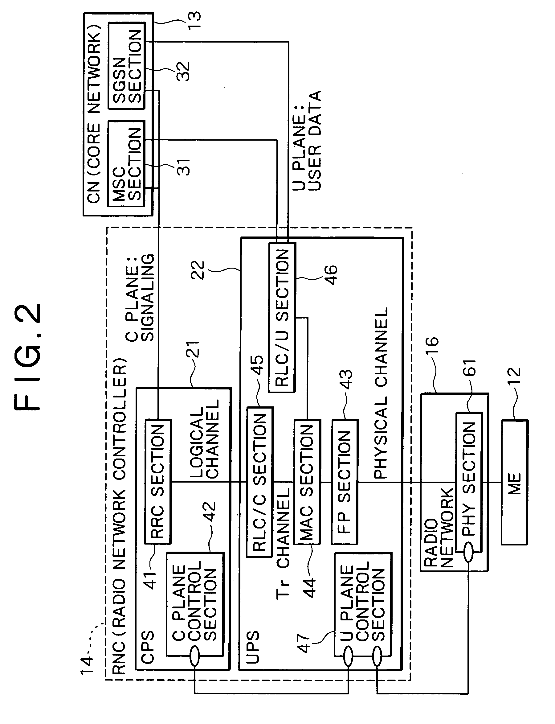
[0038] Referring now to the accompanying drawings, the preferred embodiments of the present invention will be described. FIG. 2 is a block diagram showing the structure of a mobile communication system, which includes a radio access network according to the invention.

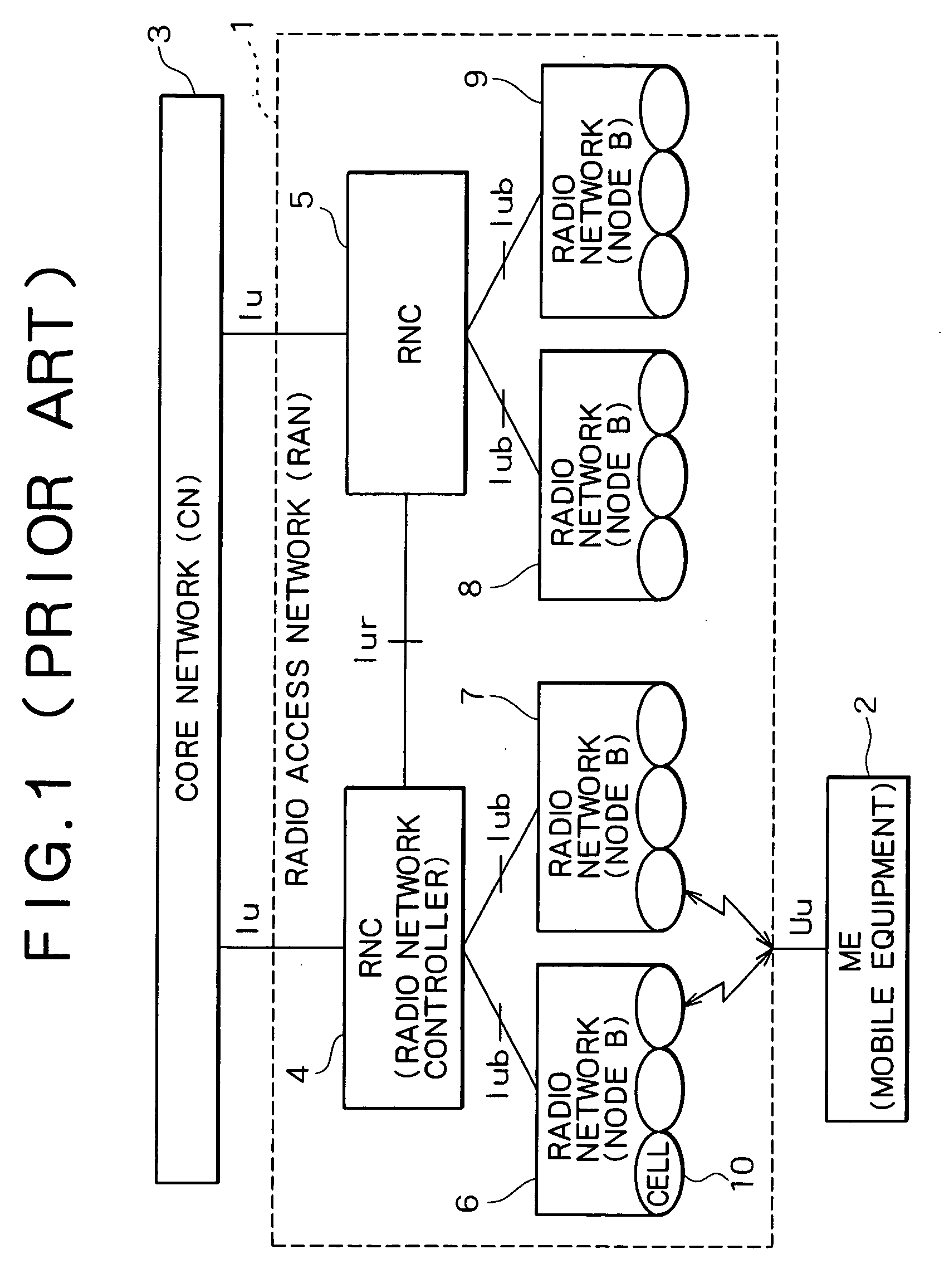
[0039] Similarly to the conventional system shown in FIG. 1, a mobile communication system according to the invention comprises a radio network 16 connected to a mobile equipment (ME) 12, a radio network controller (RNC) 14 for managing a radio resource to control the hand-over by controlling the radio network 16, and a core network (CN) 13 connected to the RNC 14 for providing the circuit exchange service and / or the packet exchange service. A radio access network (RAN) comprises the RNC 14 and the radio network 16. In FIG. 2, only an RNC 14, a radio network 16 and an ME 12 are represented. Generally, RNCs, radio networks and MEs are employed in a mobile communication system. Specifically, RNCs 14 are connected to the C...

second embodiment

[0056] In a radio access network according to the invention, a response identifier is included, adding to the control command. As a result, one of the U plane control section 47 and the C plane control section 42 extracts a set of a protocol entity identifier, a response identifier and a control command from the received control information, and stores a set of the protocol identifier and response identifier thus extracted in the storage areas of the control sections 47 and 42. Then, the one of the U plane control section 47 and the C plane control section 42 sends the control command to the respective protocol entities included in the control information in the sequence of extraction, and furthermore generates control information from the confirmation response received from the respective protocol entities to the control command in accordance with the response identifier extracted, and finally sends the control command to the other of the U plane control sections 47 and the C plane...

third embodiment

[0069] In the following, the function of the radio access network in the third embodiment will be described. FIG. 8 is a flow diagram showing the process executed between the U plane control section 47 and the C plane control section 42, and FIG. 9 shows an example of control information in the case when the U plane control section 47 sends the acquired control object identifier. FIG. 10 shows an example of control information in the case when the C plane control section 42 sets the radio network and the cell just after starting UPS.

[0070] The U plane control section 47 acquires the control object identifier for identifying the control object of a protocol entity in the timing of the UPS starting (step S301), and stores the resource managed by UPS 22 and resource identifier for identifying the resource in the storage area after assigning them to each other (step S302). Moreover, the U plane control section 47 sends the control information including all of the acquired control object...


PUM


Abstract

An RNC is divided into a plurality of user plane servers (UPSs) for executing the transmission control of user's data and a control plane server (CPS) for executing the transmission control of a control signal for transmitting user's data. A C plane control section for executing the transmission control of the control signal for transmitting the user's data is disposed in the CPS, and similarly a U plane control section for executing the transmission control of the user's data is disposed in each of the UPSs. A logical connection for transmitting control information is interposed between the U plane control section and the C plane control section. Hence, such a system, in which both the function of the C plane control and the function of the U plane control in the radio access controller (RNC) are physically divided into a plurality of devices, provides a simple control system, thereby making it possible to rapidly exchange the control information between the protocol entities.

Description

[0001] 1. Technical Field of the Invention[0002] The present invention relates to a radio access network (RAN) and to an operation control method for the same. In particular, the present invention relates to an improvement of a radio network controller (RNC) in a W-CDMA (Wideband-Code Division Multiple Access) cellular system.[0003] 2. Description of the Related Art[0004] FIG. 1 is a block diagram showing the structure of a mobile communication system including a conventional radio access network, i.e., a W-CDMA communication system.[0005] As shown in FIG. 1, a radio access network (RAN) 1 comprises radio network controllers (RNCs) 4, 5 and node B's 6 to 9. The RAN 1 is connected to a mobile equipment (ME) 2 via a Uu interface (radio interface) and to a core network (CN) 3 via an Iu interface, where the CN 3 is an exchanger network providing a circuit exchanging service or packet exchanging service. The interface between one of node Bs 6 to 9 and one of RNCs 4, 5 is called Iub, and ...

Claims


Application Information

Patent Timeline
IPC IPC(8): H04L12/24H04L12/28H04W76/02H04W88/12
CPCH04L12/24H04W88/12H04L41/00H04L12/28
Inventor KIKUCHI, TSUNEYUKI
Owner NEC CORP
Why Eureka
Try Eureka