Apparatus and method for manufacturing optical objects

a manufacturing method and optical object technology, applied in the direction of grinding machines, instruments, material analysis, etc., can solve the problems of insufficient accuracy, inconvenient use of polishing forms, and inability to achieve high-concave surfaces

Inactive Publication Date: 2009-07-07
NEDERLANDSE ORG VOOR TOEGEPAST-NATUURWETENSCHAPPELIJK ONDERZOEK (TNO) +1
View PDF13 Cites 9 Cited by
  • Summary
  • Abstract
  • Description
  • Claims
  • Application Information

AI Technical Summary

Benefits of technology

[0035]With such a method, rapidly, simply and accurately, optical objects can be worked and / or formed.

Problems solved by technology

This is why this manufacturing method is relatively expensive, labor intensive, time consuming and not always sufficiently accurate.
Use of a polishing form is then disadvantageous because with it, at least on a first side, only symmetrically ground, substantially spherical or toric surfaces with parabolic or hyperbolic cross sections can be obtained.
Further, this method is not particularly suitable for grinding and polishing highly concave surfaces.
For this method too, it holds that it is relatively expensive and time-consuming and, moreover, not always sufficiently accurate, while furthermore, each time, intermediate measurements are to be performed, during which the element is to be taken from a holder and the operation is to be stopped.

Method used


Image

  • Apparatus and method for manufacturing optical objects
  • Apparatus and method for manufacturing optical objects
  • Apparatus and method for manufacturing optical objects

Examples


Embodiment Construction

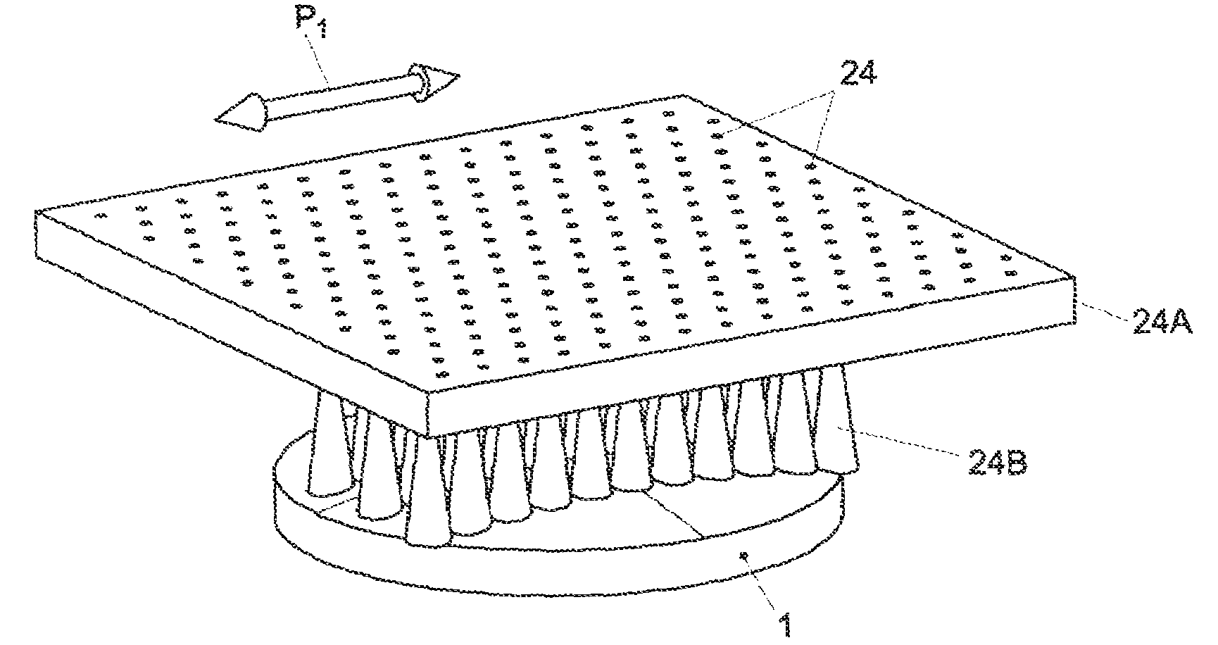
[0054]In this description, identical or corresponding parts have identical or corresponding reference numerals. In this description, as examples, mainly apparatus and methods are described for forming optical objects such as lenses, more in particular ophthalmic objects such as spectacle glasses and contact lenses, and forming elements therefor such as molds and parts thereof. However, such apparatus and methods can also be used for other optical elements, for instance precision optics, mirrors and the like. Optical elements and optical forming elements also be further indicated as optical objects. The optical objects shown in the drawing have substantially circular aspects. From them, if desired, final objects such as spectacle glasses can be cut. However, the optical objects and the pre-forms therefor can naturally also have different forms.

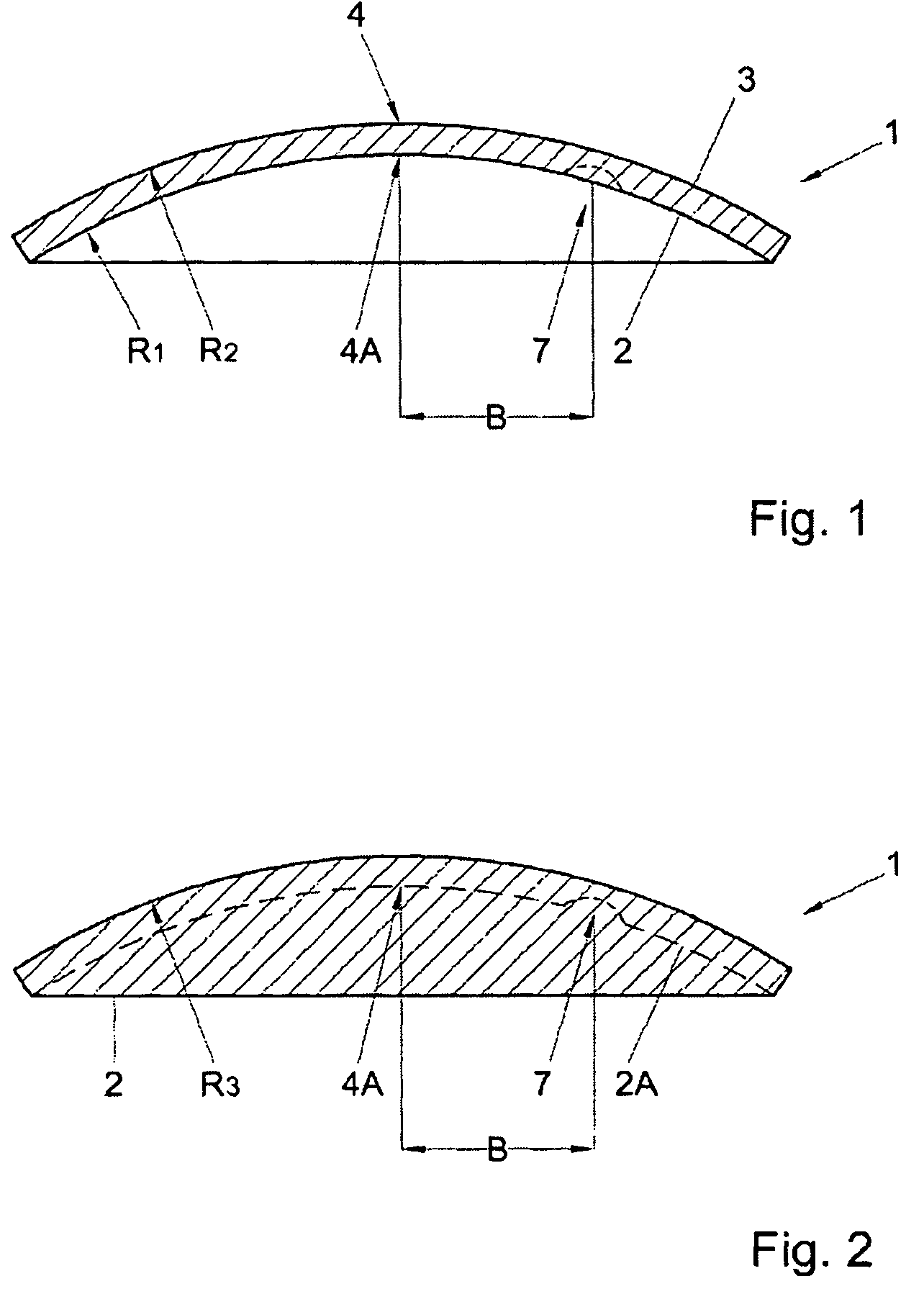
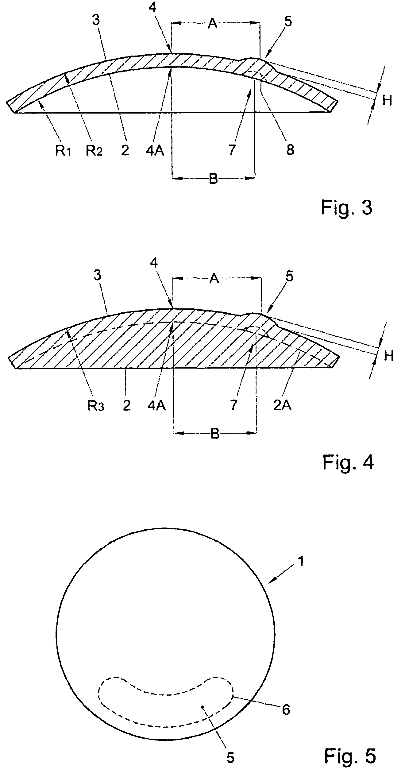
[0055]In FIG. 1, a pre-form 1 for an optical element is shown, in cross section. This pre-form 1 is manufactured from, for instance, transpare...


PUM

PropertyMeasurementUnit
pressureaaaaaaaaaa
pressureaaaaaaaaaa
pressureaaaaaaaaaa

Abstract

The invention relates to an apparatus for forming or working optical elements and/or optical forming elements (1) comprising a working apparatus (18) for forming surfaces of form parts by machining or an abrasive technique, wherein at least one measuring device (17) is provided for measuring changes in form and/or surface roughness of said surface when said surface is being worked and, on the basis thereof controlling said working apparatus (18).

Description

[0001]This application is the U.S. National Phase of International Application Number PCT / NL2003 / 000946 filed on Dec. 30, 2003, which is incorporated herein by reference.[0002]The invention relates to an apparatus for forming or working optical elements and / or optical forming elements.[0003]The invention further relates to a method for forming or working optical elements and / or forming elements.[0004]Further, the invention relates to optical elements or forming elements therefor such as molds.BACKGROUND OF THE INVENTION[0005]It is known from practice to manufacture optical elements and / or forming elements such as lenses, spectacle glasses, molds and the like from a pre-form, manufactured from, for instance, organic or mineral glass which pre-form, on a first side, has a substantially flat or slightly concave, spherical surface with a relatively large bending radius, and, on a second, opposite side, a convex surface with a relatively small bending radius. The convexity of, in particu...

Claims


Application Information

Patent Timeline
Patent Type & Authority Patents(United States)
IPC IPC(8): B24B49/00B24C5/04B24B51/00B24B13/005B24B49/12B24C1/00B24C1/08B24C3/02
CPCB24B13/005B24B49/12B24C3/02B24C1/08B24C1/00
Inventor BRUG, HEDSER VANDE HAAN, HUGO ANTON MARIEKORPERSHOEK, JACOBUS JOHANNESSAUNDERS, IAN J.
Owner NEDERLANDSE ORG VOOR TOEGEPAST-NATUURWETENSCHAPPELIJK ONDERZOEK (TNO)
Why Eureka
Try Eureka