Airtight container

a container and airtight technology, applied in the field of hermetically sealed containers, can solve the problems of unsatisfactory hermetic seals of the above conventional art teachings, difficult to bring the inside surface of the groove into close contact with the surface of the protruding protruding, and the lid body cannot be closed, etc., to achieve the effect of outstanding hermetic sealing capability

Inactive Publication Date: 2004-07-01
YOSHIDA KOGYO KK
View PDF7 Cites 18 Cited by
  • Summary
  • Abstract
  • Description
  • Claims
  • Application Information

AI Technical Summary

Benefits of technology

0020] By providing a plurality of sealing mechanisms, it becomes possible to, for example, provide seals in multiple folds and it is possible to ensure a further outstanding hermetic sealing capability.

Problems solved by technology

According to the above-described conventional art, since the inside surface of the groove and the surface of the protrusion, which are formed integrally with the container body and the lid body formed of synthetic resin material and which are made to be in close contact with each other for a hermetic seal, are formed from synthetic resin material, it is difficult to bring the inside surface of the groove into close contact with the surface of the protrusion with no space between them, because of the rigidity of the synthetic resin material itself.
Therefore, the hermetic seals of the above conventional art teachings are unsatisfactory in a case where high hermetic sealing capability is required, even though they may be satisfactory for cases where the extent of hermetic sealing capability required is not so large.
However, this gives rise to a problem that the lid body can not be closed or the opening and closing of the lid becomes difficult.
On the other hand, if the degree of contact is set loose in order to make it easy to manipulate the lid body, then this gives rise to a problem that a sufficient sealing capability cannot be obtained.
Accordingly, there arise other problems that the cost increases and the productivity decreases.

Method used


Image

  • Airtight container
  • Airtight container
  • Airtight container

Examples


Embodiment Construction

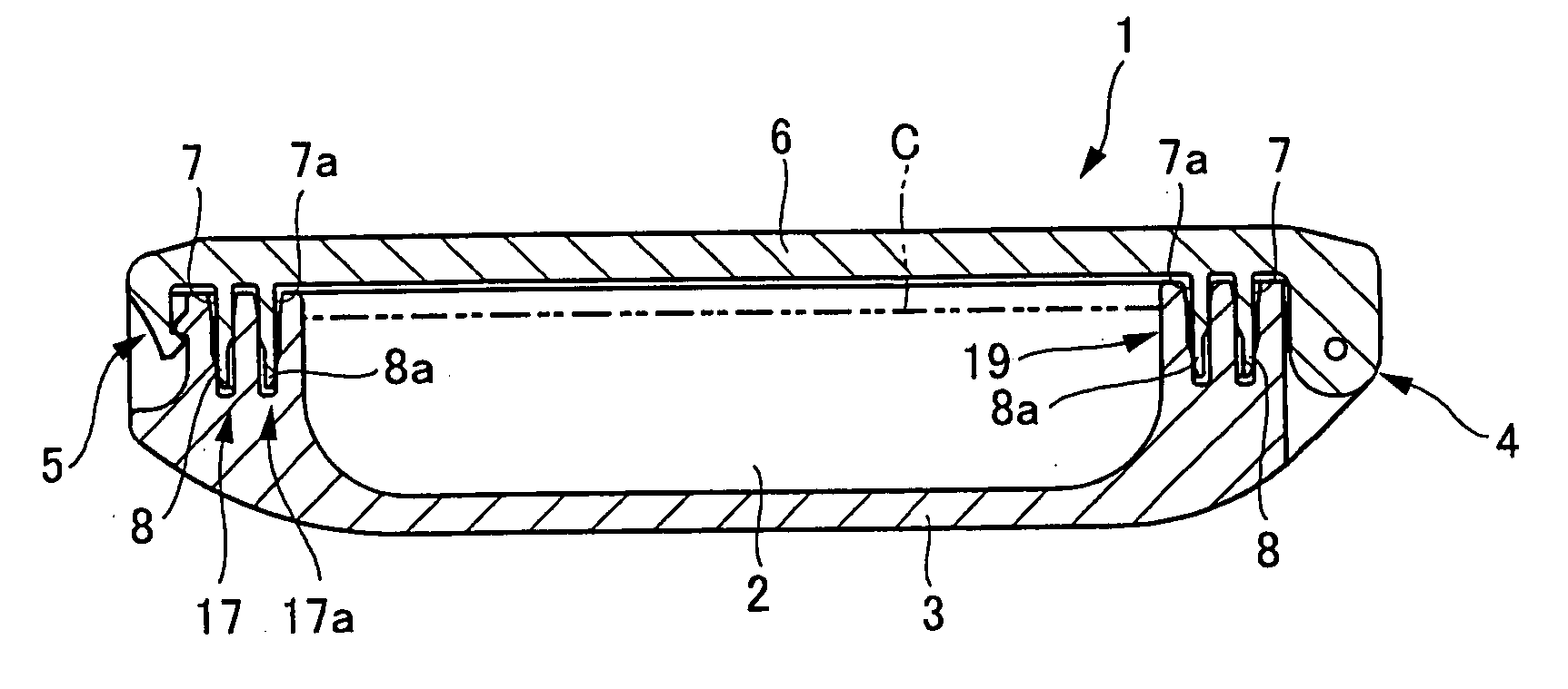
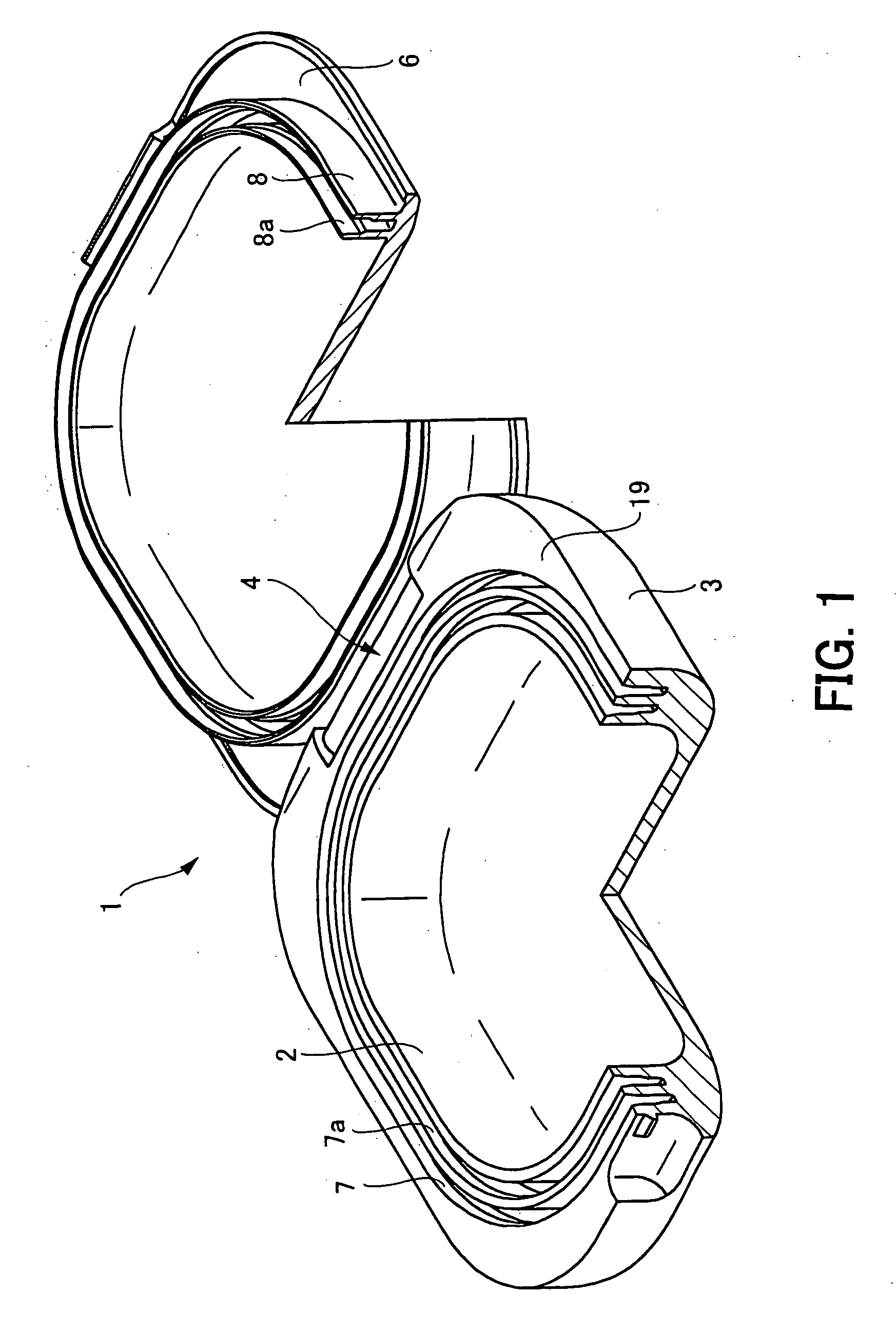
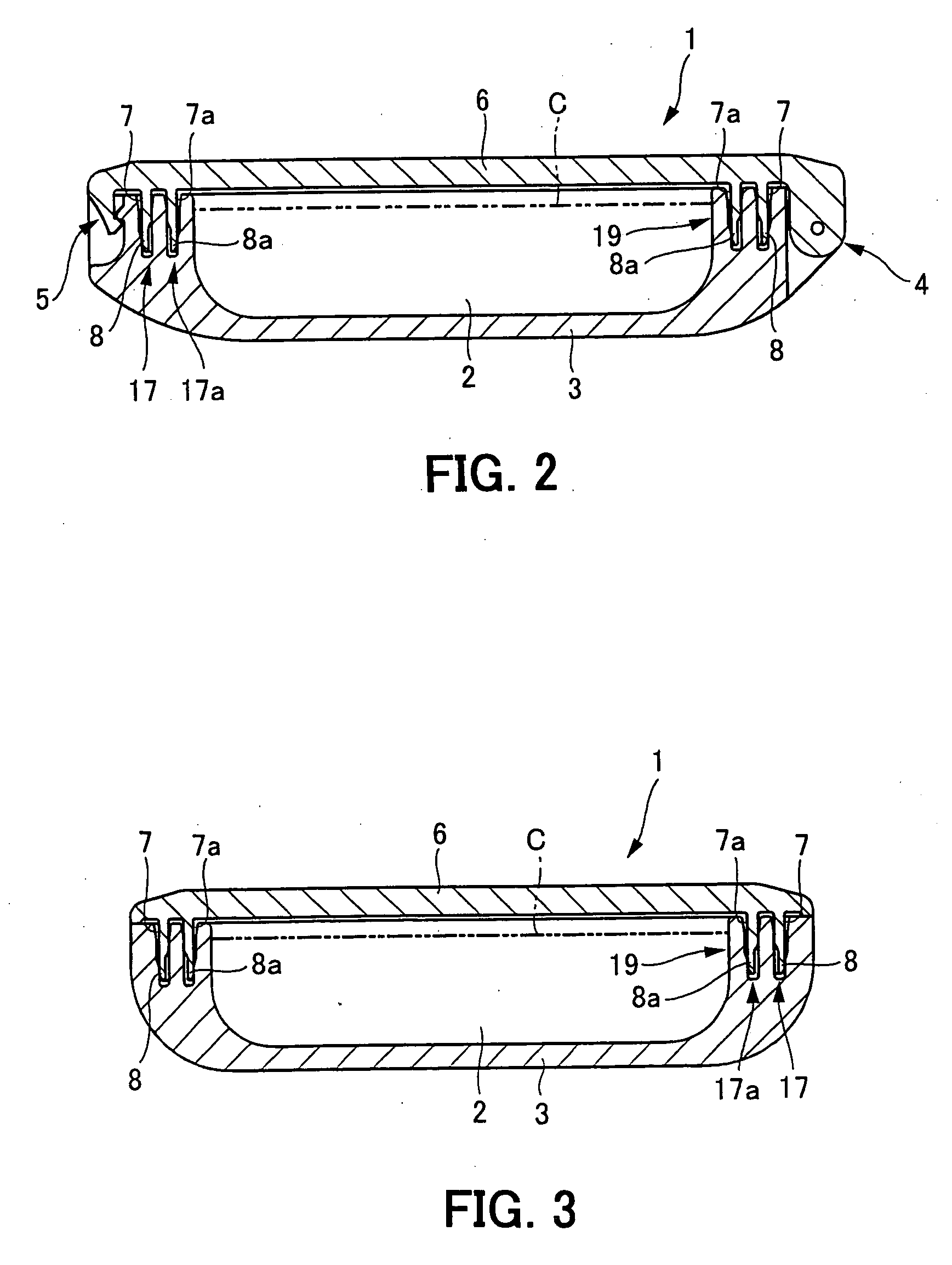
[0021] A hermetically sealed container in accordance with an embodiment of the present invention will hereinafter be described in detail with reference to the accompanying drawings. FIG. 1 through FIG. 4 show a portable cosmetic container 1, as an example of the hermetically sealed container, filled with a cosmetic substance C that includes a volatile component. As shown in the figures, this cosmetic container 1 mainly comprises a synthetic resin container body 3 formed with a storage section 2 containing the cosmetic substance C that includes a volatile component, and a synthetic resin lid body 6 which is pivotally coupled to one end of the container body 3 by a hinge 4 so as to permit opening and closing of the container body 3, and which is disengageably engaged to the other end of the container body 3 by hook means 5 so as to retain the container body 3 in a closed condition.

[0022] Basically, the cosmetic container 1 of the present embodiment is configured so that annular sealin...


PUM


Abstract

A hermetically sealed container comprises sealing mechanisms (17, 17a) wherein upper sealing surfaces (11, 11a) and lower sealing surfaces (12, 12a) are provided in inward peripheral wall surfaces (9, 9a) and outward peripheral wall surfaces (10, 10a), respectively, of annular sealing grooves integrally formed with a container body (3) misaligned from each other in the height direction of the container body, and upper sealing parts (15, 15a) and lower sealing parts (16, 16a) are provided respectively in upper parts (13, 13a) and lower parts (14, 14a) of annular sealing protrusions formed integrally with a lid body (6), and the upper parts of the annular sealing protrusions are formed to be of high rigidity to make the upper sealing parts frictionally contact the upper sealing surfaces, and the lower parts of the annular sealing protrusions are formed to be flexibly deformable and of low rigidity to make the lower sealing parts be resiliently pressed against the lower sealing surfaces.

Description

[0001] The present invention relates to a hermetically sealed container having a sealing mechanism that can be formed integrally with a container body and a lid body made of synthetic resin and is thus low in cost and has excellent productivity features, and that achieves high hermetic sealing capability while ensuring smooth opening and closing of the lid body.[0002] Some of the various types of containers, such as cosmetic containers, that are generally formed of synthetic resin material require extremely high hermetic sealing capability because, for example, the contents may include volatile components. A structure which ensures a hermetic seal for such containers is known to comprise, for example, an annular groove integrally formed in either a container body or a lid body, and an annular protrusion formed which is integrally with the other of the container body or the lid body and is inserted into the annular groove. By maintaining close contact between the inside surface of th...

Claims


Application Information

Patent Timeline
Patent Type & Authority Applications(United States)
IPC IPC(8): A45D33/00B65D53/02F16J15/04
CPCA45D2200/051A45D33/006
Inventor YUHARA, YUKITOMO
Owner YOSHIDA KOGYO KK
Why Eureka
Try Eureka