Multi-axis cartesian guided parallel kinematic machine

a parallel kinematic machine and multi-axis technology, applied in the direction of programmed manipulators, metal-working machine components, manufacturing tools, etc., can solve the problems of poor rigidity and motion precision of the parallelogram guiding mechanism (63) and the limited position accuracy of the gripping device or the tool head (58)

Inactive Publication Date: 2004-07-01
CHEN JENG SHYONG
View PDF8 Cites 78 Cited by
  • Summary
  • Abstract
  • Description
  • Claims
  • Application Information

AI Technical Summary

Problems solved by technology

Control of such a five axis machine requires much expansive and sophisticated software and hardware.
The position accuracy of the gripping device or tool head (58) is limited due to the motion inaccuracy of the universal joint (56) and the length error of the arm (50).
However, because there are multiple high compliant pivot joints involved in the guiding mechanism (63), the rigidity and motion precision of the parallelogram guiding mechanism (63) is not good.
The Cartesian position accuracy of the mobile platform (62) is limited due to the joint locations errors and initial length errors of the leg (66).

Method used


Image

  • Multi-axis cartesian guided parallel kinematic machine
  • Multi-axis cartesian guided parallel kinematic machine
  • Multi-axis cartesian guided parallel kinematic machine

Examples


first embodiment

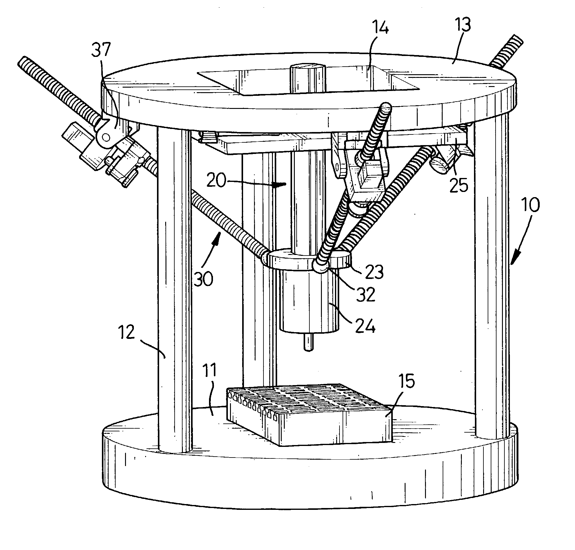
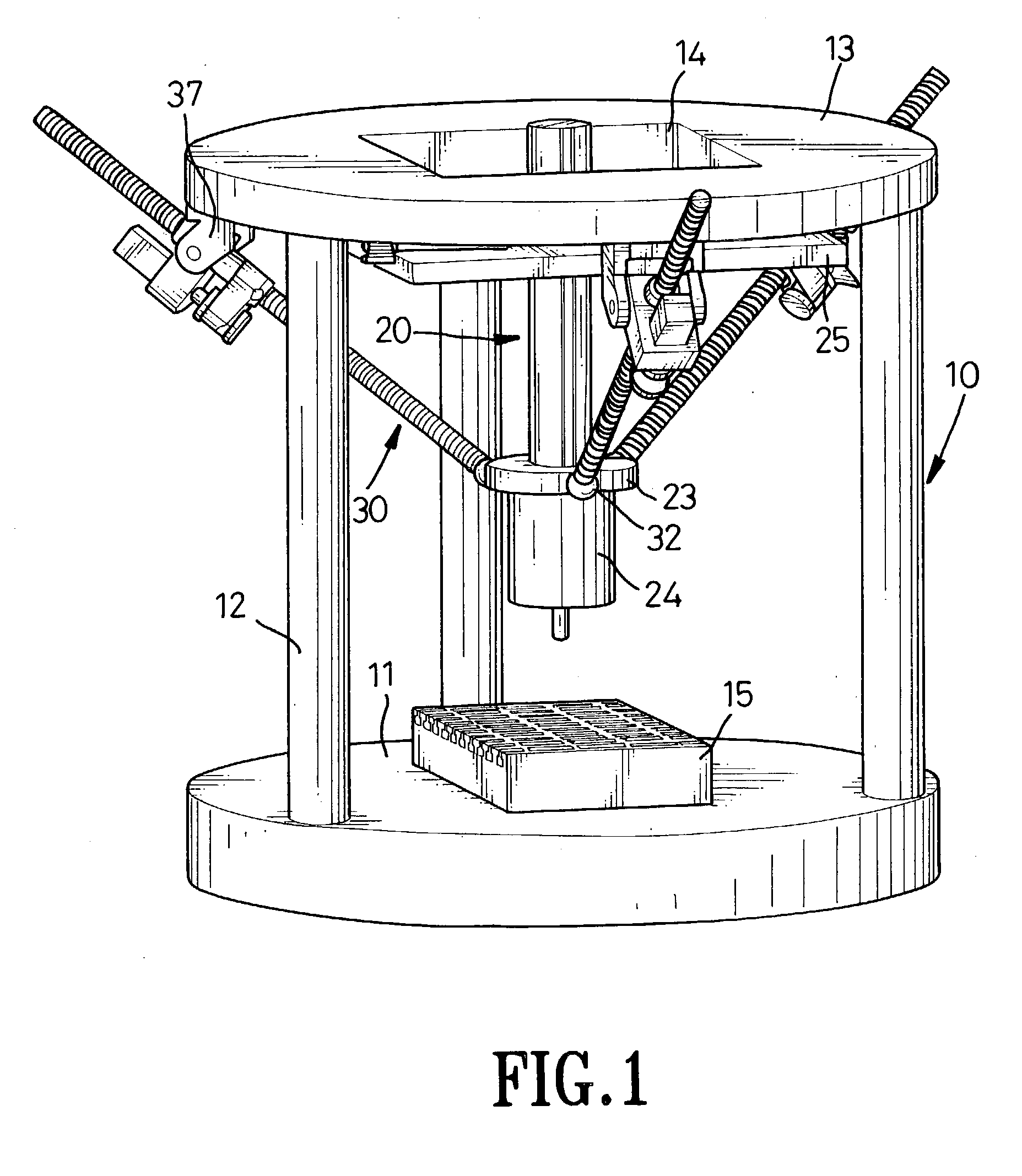
[0023] The three-linear-axis Cartesian guiding mechanism assembly (20) is moveably attached to the frame (10). With reference to FIGS. 1 and 2, the three-linear-axis Cartesian guiding mechanism assembly (20) comprises two first-Cartesian-axis guiding tracks (251), four x-y sliding pads (252), two second-Cartesian-axis guiding tracks (253), a x-y motion table (25), a third-Cartesian-axis guiding busing (22), and a z-axis movable arm (21). The x-y motion table (25) is moveably attached to the bottom of the base platform (13). In the first embodiment, two first-Cartesian-axis guiding tracks (251) are in-parallel and firmly secured on the base platform (13) in that the first-Cartesian axis guiding tracks (251) are parallel to the surface of the base platform (13). The two parallel first-Cartesian-axis guiding tracks (251) then define the motion direction of the first Cartesian linear axis said the X-axis. Two x-y sliding pads (252) are movably attached to each first-Cartesian-axis guidi...

third embodiment

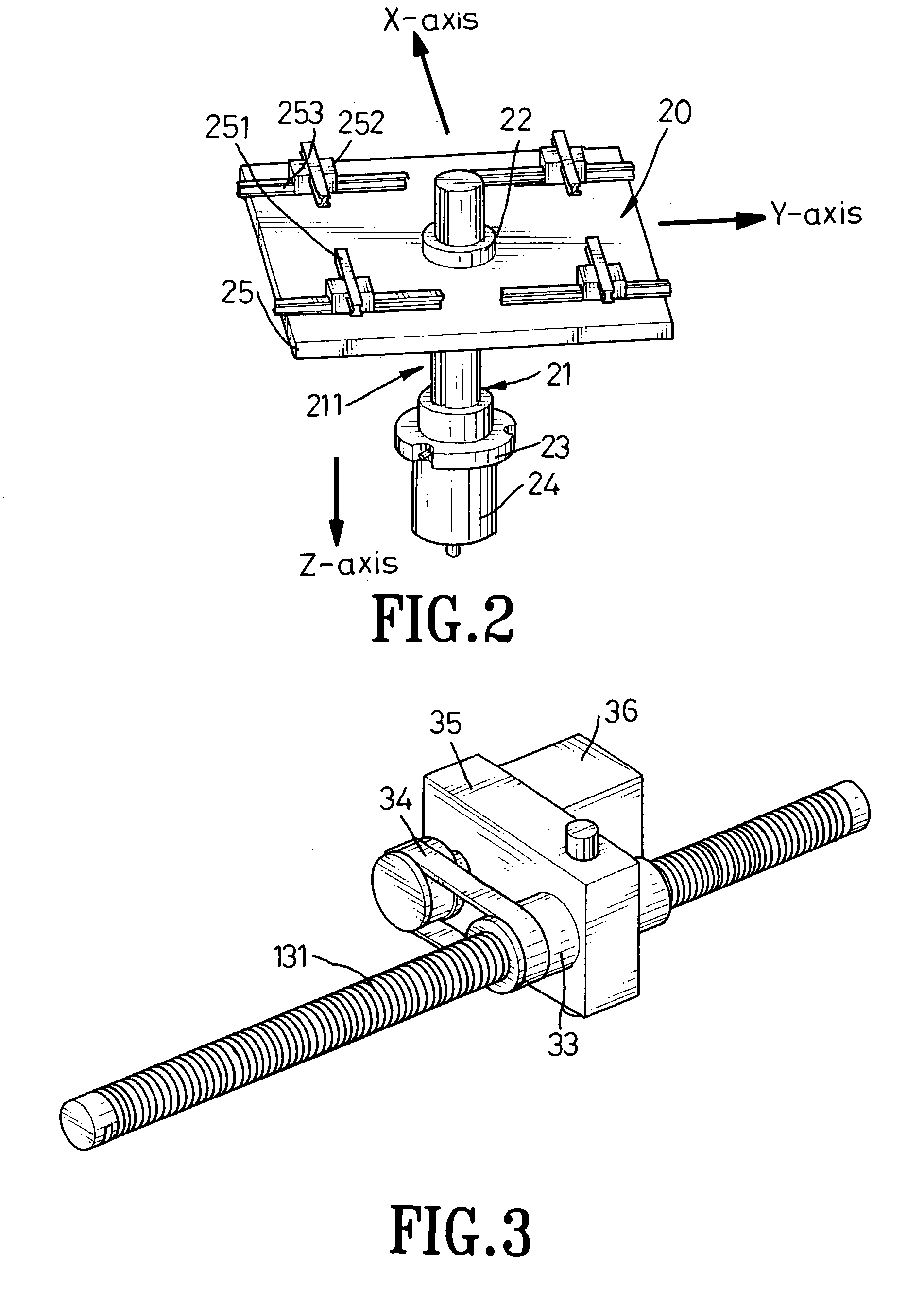
[0030] With reference to the FIG. 5, the three-axis Cartesian guided parallel kinematic machine comprises a base platform (13), a three-linear-axis Cartesian guiding mechanism assembly (20A), three driving strut assemblies (30B), and a motion platform (23). Each driving strut assembly (30B) is a sliding leg comprising of a fixed length rod (31B), a universal joint (37), a ball joint (32), a motion slide (31B1), four sliding pads (31B2), and two guiding tracks (31B3). One end of the rod (31B) is pivotally mounted to the motion platform (23) by a ball joint (32). The opposite end of the rod (31) is pivotally connected to the motion slide (31B1) using a universal joint (37). The motion direction of the motion slide (31B 1) is defined by two parallel guiding tracks (31 B2) firmly mounted on the post (12A). Four sliding pads (31B3) are used to connect the motion slide (31B1) to the guiding tracks (31B2).

[0031] When the motion slides (31B 1) of the driving strut assemblies (301B) are actu...

fourth embodiment

[0032] With reference to the FIGS. 6 and 7, the three-axis parallel kinematic machine comprises a frame (10A), a base platform (13), a three-linear-axis Cartesian guiding mechanism assembly (20A), three driving strut assemblies (30A), a motion platform (23), and a plate (26). The frame (10A) is composed of a bottom base (101) and a wall (102). The base platform (13) is in-horizontal mounted to and supported by the frame (10A). The three-linear-axis Cartesian guiding mechanism assembly (20A) is attached to the base platform (13) in that the first-axis guiding tracks (251) is parallel to the surface of the base platform (13). A motion platform (23) is mounted firmly to one end of the z-axis movable arm (21), while a plate (26) is mounted firmly to the opposite end of the z-axis movable arm (21). One end of each driving strut assembly (30A) is connected to the plate (26) with a ball or universal joint (32). The other end of each driving strut assembly (30A) is connected to the wall (10...


PUM

PropertyMeasurementUnit
lengthaaaaaaaaaa
relative rotationaaaaaaaaaa
displacementsaaaaaaaaaa

Abstract

A multi-axis Cartesian guided parallel kinematic machine has a frame, a base platform, a multi-axis Cartesian guiding mechanism assembly, multiple driving strut assemblies and a motion platform. The motion platform is connected to the base platform through the driving strut assemblies and the multi-axis Cartesian guiding mechanism assembly. The multi-axis Cartesian guiding mechanism assembly has multiple linear guiding mechanisms and rotary guiding mechanisms that are in-serial linked and arranged in orthogonal to each other according to the Cartesian coordinate system. The multiple driving strut assemblies are in-parallel connected to the base platform and the motion platform using pivot joints. Each driving strut assembly is a telescoping strut assembly or a sliding strut assembly. When the driving strut assemblies are actuated, the motion platforms can be driven to a desired position in the Cartesian workspace with a controllable platform orientation relative to the frame.

Description

[0001] 1. Field of the Invention[0002] The present invention relates to a multi-axis parellel kinematic machine for multi-axis positioning or machining, and more particularly to a multi-axis parellel kinematic machine that can be controlled easier and more precisely in the Cartesian coordinate workspace with controllable orientation.[0003] 2. Description of Related Art[0004] With reference to FIG. 10, a conventional parallel kinematic machine comprises an extendable arm (50) and three control struts (52). One end of the extendable arm (50) is pivoted by a universal joint (56) that is connected to a stand (51). The opposite end of the extendable arm (50) is fixed to a mobile head (57). A gripping device or a tool head (58) is attached to the mobile head (57). Each control strut (52) is a cylinder with a piston. One end of each control strut (52) is pivotally connected to the stand (51) by a joint (53) such as a ball joint. The other end of each control strut (52) is pivotally connect...

Claims


Application Information

Patent Timeline
Patent Type & Authority Applications(United States)
IPC IPC(8): B23Q1/54B25J17/02
CPCB23Q1/5462B25J17/0266Y10T409/307672B25J9/0066Y10T409/309576B25J9/0069
Inventor CHEN, JENG-SHYONG
Owner CHEN JENG SHYONG
Why Eureka
Try Eureka