Device for transmitting a movement having a parallel kinematics transmission structure providing three translational degrees of freedom

a technology of transmission structure and movement, applied in the field of movement transmission, can solve the problems of force-feedback devices moving and invading the gaming industry

Inactive Publication Date: 2006-11-09
CONTI FRANCOIS
View PDF5 Cites 10 Cited by
  • Summary
  • Abstract
  • Description
  • Claims
  • Application Information

AI Technical Summary

Benefits of technology

[0014] According to an embodiment, there is provided a device or assembly for transmitting a movement, comprising at least one moveable member which is coupled to at least one parallel kinematics transmission structure each providing three translational degrees of freedom; at least one rotative actuator which is coupled to the parallel transmission structure over a control arm such that any translational movement is transmitted into a rotational movement, or vice versa, wherein the rotative act...

Problems solved by technology

Moreover, force-feedback devices are moving to the consumer market...

Method used


Image

  • Device for transmitting a movement having a parallel kinematics transmission structure providing three translational degrees of freedom
  • Device for transmitting a movement having a parallel kinematics transmission structure providing three translational degrees of freedom
  • Device for transmitting a movement having a parallel kinematics transmission structure providing three translational degrees of freedom

Examples


Embodiment Construction

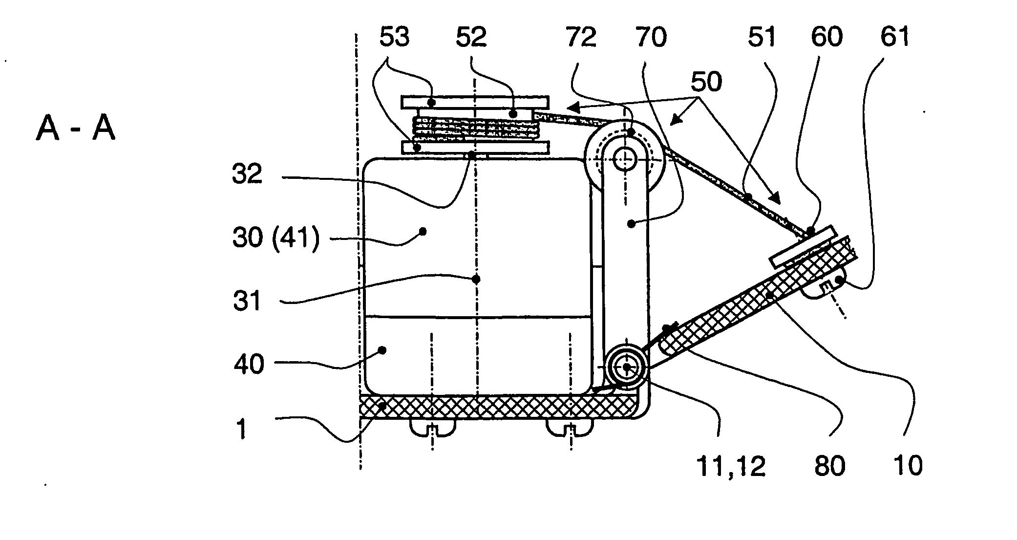
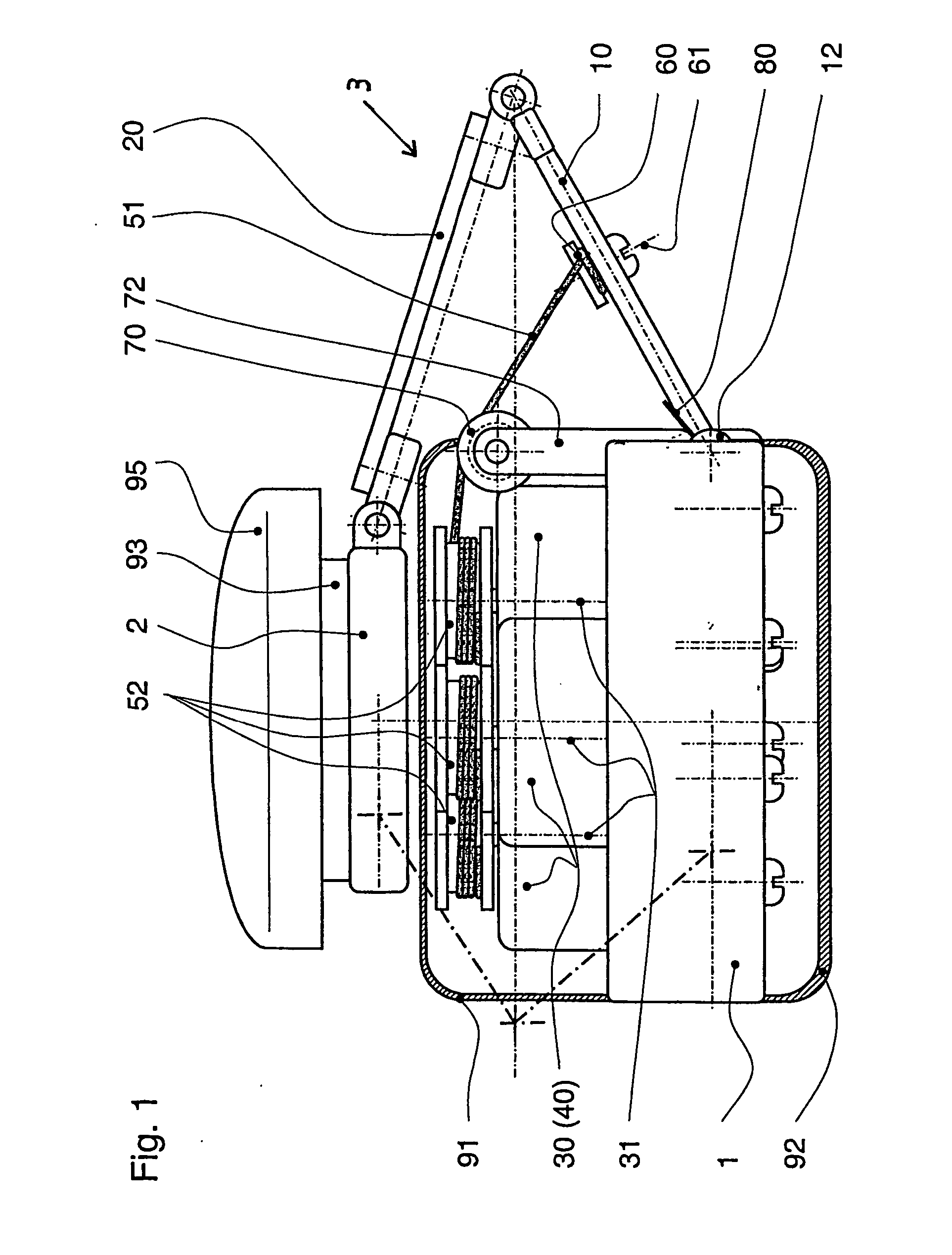
[0028]FIG. 1 illustrates the basic constituent parts of a movement transmission device or assembly for use in a haptic device, according to a first embodiment of the present invention. Before proceeding further with the detailed description of FIG. 1, however, a few items of the embodiments will be discussed.

[0029] According to one of the embodiments, there is provided a device for transmitting a movement between an input side and an output side, or vice versa, comprising: at least one moveable member arranged at one of the input and output sides, the moveable member being coupled to at least one parallel kinematics transmission structure each providing three translational degrees of freedom; at least one rotative actuator arranged at the other of the input and output sides, the rotative actuator being coupled to the parallel kinematics transmission structure over a control arm such that any translational movement is transmitted into a rotational movement, or vice versa, wherein th...


PUM


Abstract

The invention is directed to a device for transmitting a movement having a parallel kinematics transmission structure (3) providing three translational degrees of freedom, said structure comprising one base member (1), one moveable member (2), at least one rotative actuator (30) arranged on the base member (1), parallel kinematics chains coupling the base member to the moveable member, each chain comprising a pivoting control arm (10), wherein the rotary motion of the at least one rotative actuator (30) is transmitted to a respective pivoting control arm (10) so that any translational movement of the moveable member is transmitted into a rotational movement of the control arms or vice versa, and wherein the at least one rotative actuator (30) is arranged such that its axis (31) is substantially perpendicular to the rotation axis of the control arms (10). The parallel kinematics transmission structure comprises three parallel kinematics chains, each chain comprising a pivoting control arm and a pair of parallel linking bars hingedly mounted by two rotational degrees of freedom joints at one end to an extremity of the control arm and at the other end to moveable member, thus forming a delta type arrangement, wherein each chain is provided with a respective rotative actuator and wherein the rotative actuators are arranged such that their axis are substantially parallel to each other. The movement between the rotative actuators and the control arms are transmitted by cable members (51).

Description

FIELD OF THE INVENTION [0001] The present invention relates in general to movement transmission, and for example, to a device or assembly for transmitting a movement using a parallel kinematics mechanism, to a haptic device or system of a force-reflecting control interface, such as a hand controller for computers, game consoles, simulators or other systems, and to a movement transmission device for a parallel kinematics manipulator or a parallel kinematics measuring system. BACKGROUND OF THE INVENTION [0002] The increasing need for enhanced human-computer interaction (HCI) is pushing for new interfaces that allow humans and machines to exchange a wider range of information. As one example among these new interfaces, so called haptic devices, that is, active interface devices applying tactile sensation and control to interaction with computer applications, are promised a place of choice. Haptic devices provide users with force-feedback information on the motion and / or force that they...

Claims


Application Information

Patent Timeline
IPC IPC(8): B66D1/48B25J17/02
CPCB25J9/0015B25J17/0266
Inventor CONTI, FRANCOIS
Owner CONTI FRANCOIS
Why Eureka
Try Eureka