Parallel kinematic mechanisms with decoupled rotational motions

a kinematic mechanism and rotational motion technology, applied in the field of minimal access tools, can solve the problems of non-intuitive control, increasing frequency and complexity of minimal access surgery (mis) and other minimal access procedures, and increasing complexity of minimal access procedures

Inactive Publication Date: 2019-11-07
FLEXDEX INC
View PDF0 Cites 16 Cited by
  • Summary
  • Abstract
  • Description
  • Claims
  • Application Information

AI Technical Summary

Benefits of technology

[0050]The first independent path (e.g., the first slider joint) and the second intermediate path independent path (e.g., the second slider joint) ma

Problems solved by technology

Minimally invasive surgical (MIS) and other minimal access procedures are increasing in frequency and becoming more complex, thus demanding improvements in technology to meet the needs of surgeons.
The traditional mechanical tools are difficult to use because of their lack of dexterity (i.e. the yaw and pitch rotational DoF).
While the newer tools are capable of enhanced dexterity given their extra two DoF, they present non-intuitive DoF control (input motion to output motion mapping) schemes that limit user's ability to fully exploit the tool's enhanced dexterity capability.
In addition, large size, high cost, and limited large-scale maneuverability also reduce the overall functionality of such robotic systems.
Therefore, most existing multiple DoF tools lack the design characteristics to allow for enhanced dexterity as well as desired functionality in a cost effective, compact package.
In particular, multiple DoF tools that allow for wrist-like rotations of the tool tip manipulator are important to meet the needs of modern minimal access and MIS procedures, but are not effective unless comfortable, ergonomic, and intuitive control of these additional DoF are ensured.
One challenge of using a serial kinematic mechanism design as the input joint of a surgical tool or machine or device is that of transmitting the two rotational DoF from the input joint to another location on the tool or machine or device.
Unfortunately, si

Method used


Image

  • Parallel kinematic mechanisms with decoupled rotational motions
  • Parallel kinematic mechanisms with decoupled rotational motions
  • Parallel kinematic mechanisms with decoupled rotational motions

Examples


Embodiment Construction

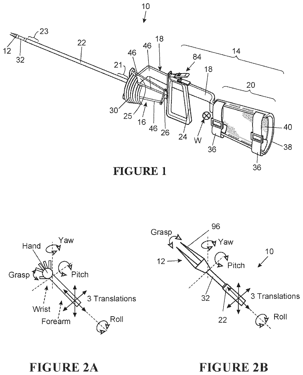
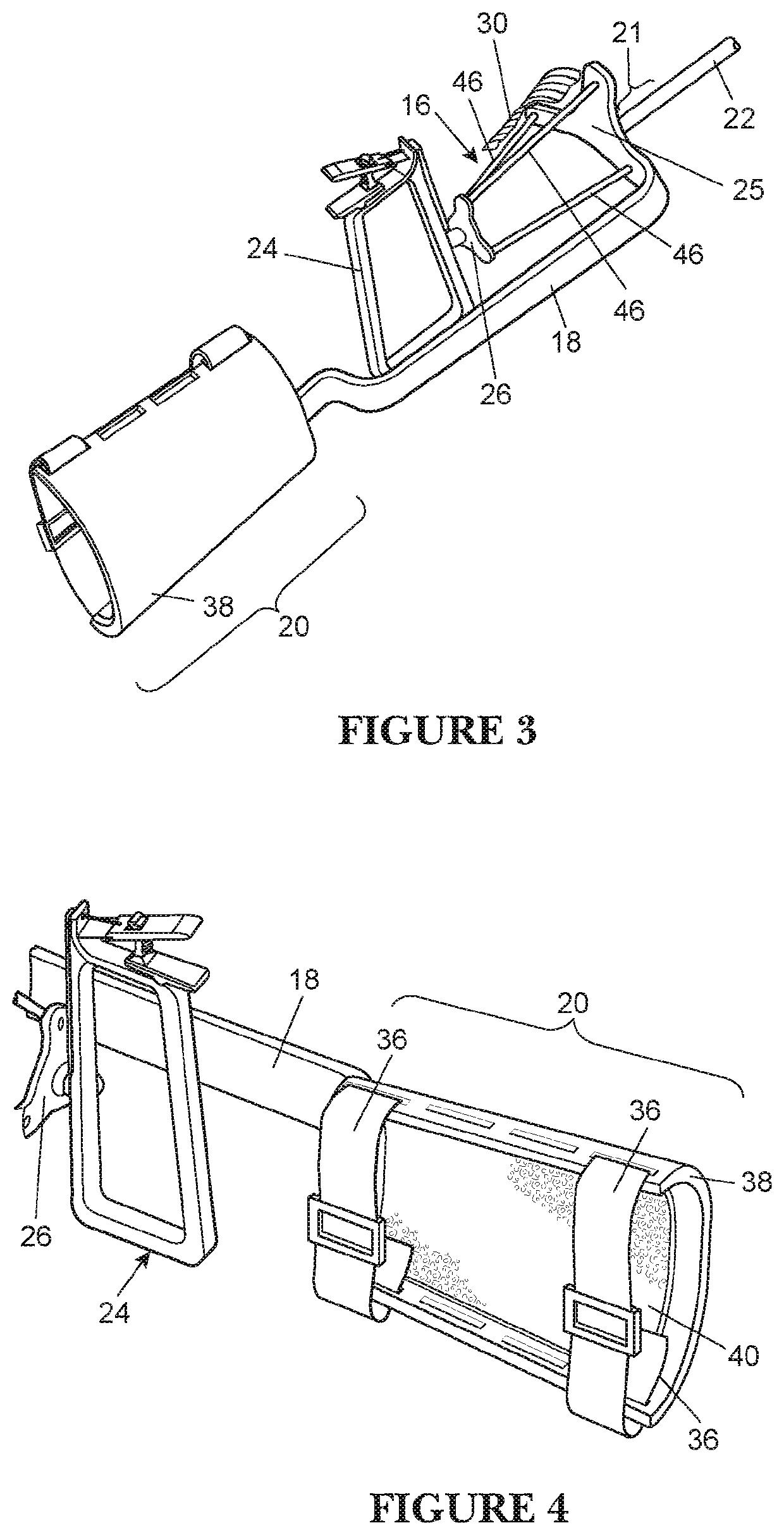
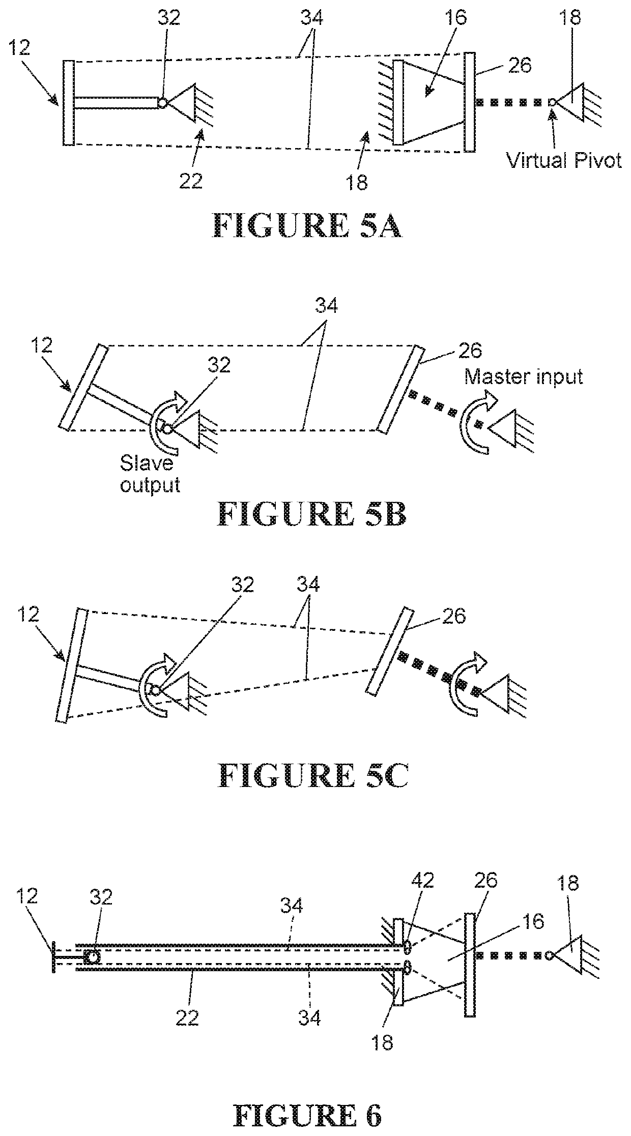
[0123]Described herein are parallel kinematic (PK) mechanism apparatuses based on a constraint map focusing on articulation motion (i.e. two orthogonal rotations). As will be described in greater detail below, although the constraint map is specific and well-defined, it serves as the basis for multiple physical embodiments that may look physically different but all incorporate the same basic underlying concept. The apparatuses and methods described herein may embody applications of the parallel kinematic constraint map shown in FIG. 26.

[0124]The constraint map shown in FIG. 26 indicates that, for a device such as a minimally invasive surgical tool which includes a frame portion and a handle portion, there may be at least two independent, non-overlapping paths of connection, which make a parallel kinematic arrangement. The frame 2603, handle 2601, intermediate body A 2605, and intermediate body B 2607 may be generally “rigid” (e.g., difficult to bend or deform). Connector 1 (2611), c...


PUM


Abstract

A parallel kinematic mechanism apparatus includes a frame, a handle and an input joint that connects having at least two independent and functionally parallel paths for transmission of motion coupling the handle to the frame. A first path includes a first intermediate body connected to the frame by a first connector and to the handle by a third connector while the second path that is independent from the first path includes a second intermediate body that is connected to the frame by a second connector and to the handle by a fourth connector. The first connector and the fourth connector both allow rotation in a first rotational direction and restrict rotation in a second rotational direction and the second and third connectors allow rotation in the second rotational direction and restrict rotation in the first rotational direction.

Description

CROSS REFERENCE TO RELATED APPLICATIONS[0001]This application is a continuation of U.S. patent application Ser. No. 15 / 054,068, filed Feb. 25, 2016, titled “PARALLEL KINEMATIC MECHANISMS WITH DECOUPLED ROTATIONAL MOTIONS,” now U.S. Patent Application Publication No. 2016 / 0256232, which is herein incorporated by reference in its entirety.INCORPORATION BY REFERENCE[0002]All publications and patent applications mentioned in this specification are herein incorporated by reference in their entirety to the same extent as if each individual publication or patent application was specifically and individually indicated to be incorporated by reference.FIELD[0003]This invention relates to a minimal access tool, such as for surgery, endoscopy, or other interventions.BACKGROUND[0004]Devices, including minimally invasive surgical tools, may be controlled by controlling the motion of multiple rigid bodies forming the device. In machines, mechanisms, robots, etc., multiple rigid bodies are often in...

Claims


Application Information

Patent Timeline
IPC IPC(8): A61B34/00A61B17/29
CPCA61B2017/00464A61B2017/2929A61B2017/00323A61B17/2909A61B2034/306A61B2017/2937A61B34/75A61B2017/2944A61B2017/2939A61B34/77A61B2017/2917A61B2017/2918A61B2017/00424A61B34/71A61B2017/2931A61B2017/00442A61B2017/00438A61B2017/291A61B34/70A61B90/53
Inventor AWTAR, SHORYABOWLES, GREGORY BRIAN
Owner FLEXDEX INC
Why Eureka
Try Eureka