Parallel kinematic device

A parallel and kinematic connection technology, applied in the direction of lifting device, transportation and packaging, lifting frame, etc., to achieve the effect of increasing rigidity, clear movement process, and simplifying the actual structure

Inactive Publication Date: 2007-11-14
弗伦茨·埃伦莱特纳
View PDF12 Cites 11 Cited by
  • Summary
  • Abstract
  • Description
  • Claims
  • Application Information

AI Technical Summary

Problems solved by technology

[0022] This document does not give any examples for the movement of larger loads or the transmission of greater forces, because between the bottom point of the movement and the actuator tha

Method used


Image

  • Parallel kinematic device
  • Parallel kinematic device
  • Parallel kinematic device

Examples


Embodiment Construction

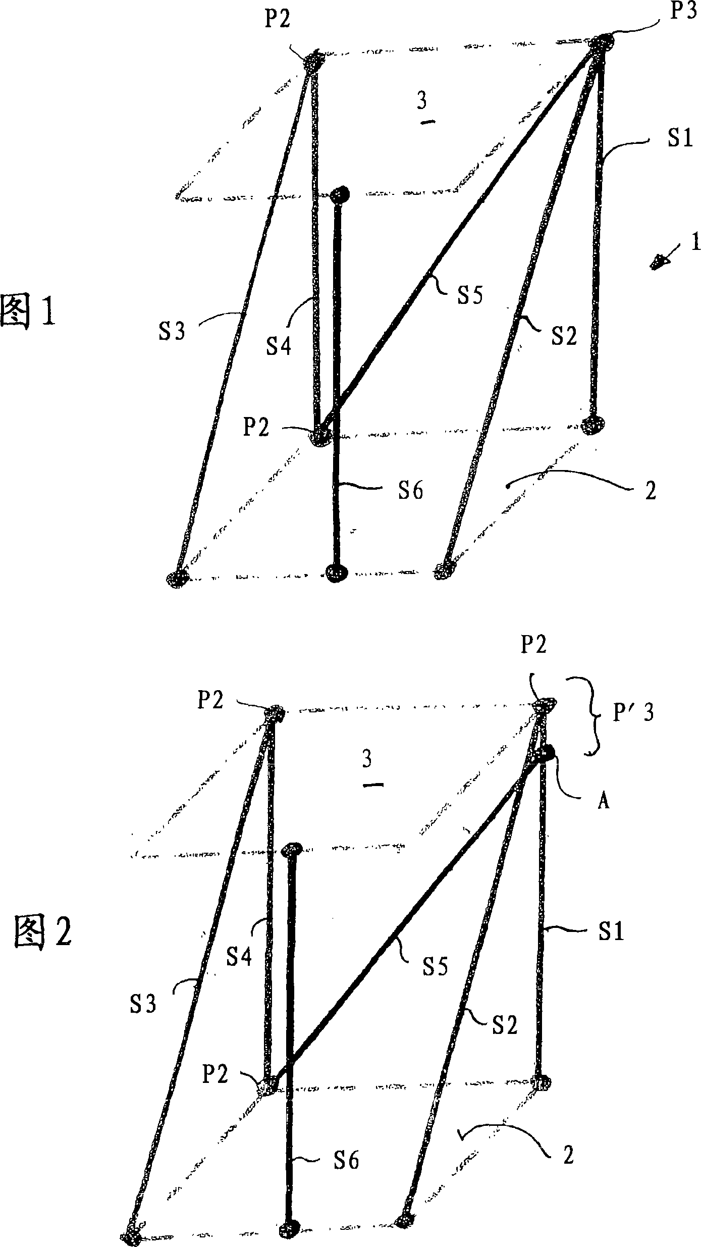
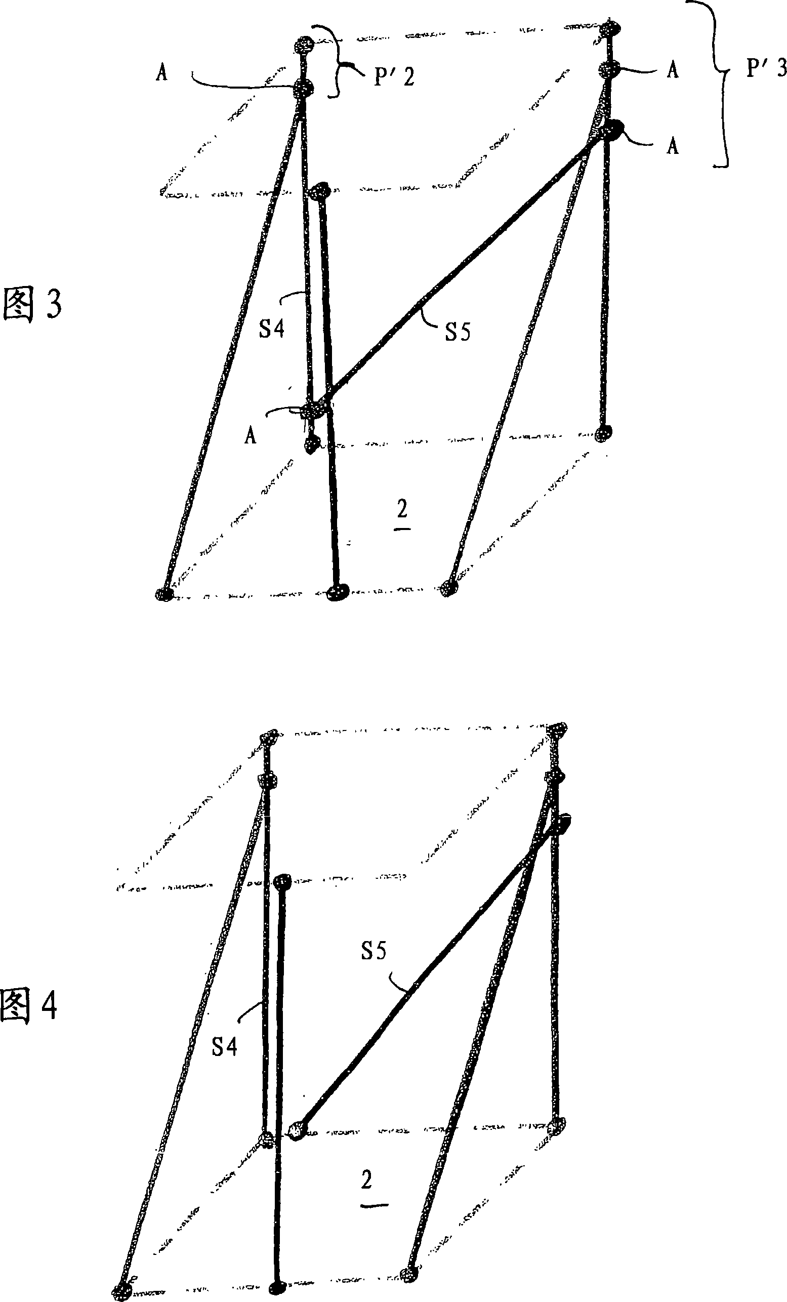
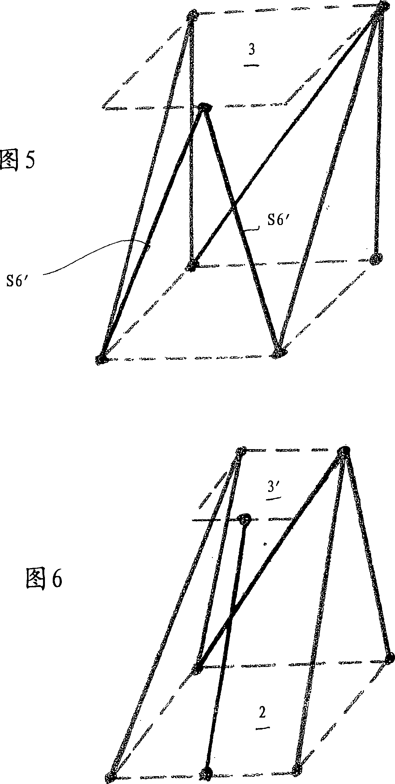
[0076] FIG. 1 shows a purely schematic illustration of the parallel kinematics according to the invention, which is designated 1 in its entirety. As mentioned above, this kinematic mechanism connects a fixed platform 2 with a movable platform 3 , wherein, unlike the serial kinematic mechanism, no intermediate platforms are provided. The designation "fixed platform" does not necessarily imply that this platform is at rest in an inertial system, the designation merely serves to distinguish from which platform the movement within the system under consideration takes place.

[0077] In this way it can be achieved that in parallel kinematics the entire kinematics consists of closed chains, i.e. there are different closed bar systems which go from one platform to the other on one path and on the other and return to the one platform from the other platform. As long as this point is associated with the tool orientation of the lathe, it is completely excluded for the serial kinematic ...


PUM


Abstract

The invention relates to the kinematic connection of a fixed platform (2) to a mobile platform (3) comprising up to six degrees of freedom in closed kinematic chains, (parallel kinematics), the connecting elements being rods, (actuators) of adjustable length, optionally consisting partially of rods of a constant length, (passive rods) and optionally cables. The invention is characterised in that three connecting elements of this type engage with a common point of one of the platforms (2, 3), forming a triple point (P3). In embodiments of the invention, said triple point can be configured as a pseudo triple point to produce a simple mechanical configuration, without losing the advantages of the invention. The inventive kinematics can be used for lifting tables, tackle for overhead conveyors, lifting robots, articulated arm-type robots, excavators, mills, cutting devices etc..

Description

technical field [0001] The invention relates to a mechanical parallel kinematic device having at least two fixed components movable relative to each other along multiple degrees of freedom, a fixed platform and a moving platform, such as lifting tables, suspension rails, lifting robots, bent arm robots , excavators, milling machines, cranes, cutting devices, measuring devices, handling manipulators, etc. Background technique [0002] Going back to all the final details of the problem of sufficiently precise and fast movement along multiple degrees of freedom between the base or base or fixed platform and the work or movable or final organization" was resolved. Here, a mechanism moves along one degree of freedom, on which another mechanism moves about another degree of freedom, etc. Depending on the number of degrees of freedom required and according to the number of mechanisms up to the final platform up to the finish, it has, for example, the desired tool in the case of m...

Claims


Application Information

Patent Timeline
IPC IPC(8): B25J17/02B25J9/04B25J18/00
CPCB66C13/08B66C23/82B25J9/0072B25J17/0266B66F7/0633B66F7/08
Inventor 弗伦茨·埃伦莱特纳
Owner 弗伦茨·埃伦莱特纳
Why Eureka
Try Eureka