Method for calibrating parallel kinematic mechanism, method for verifying calibration, program product for verifying calibration, method for taking data, and method for taking correction data for spatial posturing correction

Inactive Publication Date: 2008-04-15
SHINNIPPON KOKI
View PDF18 Cites 14 Cited by
  • Summary
  • Abstract
  • Description
  • Claims
  • Application Information

AI Technical Summary

Benefits of technology

[0002]The present invention relates to a calibration technology in a parallel kinematic mechanism which requires no measurements after posturing.
[0009]It is an object of the present invention to provide a calibration method for a parallel kinematic mechanism, a calibration verification method, a calibration verification program product, a data taking method and a correction data taking method for spatial posturing correction which require no measurement after posturing.

Problems solved by technology

However, it can be seen that the former prior art documents refer to the fact that at least one kinematic parameter cannot be acquired.
Also, the technology of the latter prior art document requires measurement after posturing, and in particular requires at least one measurement in the posture that involves difficult measurement.

Method used


Image

  • Method for calibrating parallel kinematic mechanism, method for verifying calibration, program product for verifying calibration, method for taking data, and method for taking correction data for spatial posturing correction
  • Method for calibrating parallel kinematic mechanism, method for verifying calibration, program product for verifying calibration, method for taking data, and method for taking correction data for spatial posturing correction
  • Method for calibrating parallel kinematic mechanism, method for verifying calibration, program product for verifying calibration, method for taking data, and method for taking correction data for spatial posturing correction

Examples


Embodiment Construction

[0028]A preferred embodiment of the invention will be described with reference to the appended drawings. This embodiment will be described with reference to a 6×6 parallel kinematic machine which includes six joints on an end effecter and six joints on a base, more specifically, is in the form of the Stewart platform which has direct driving actuators, i.e., struts as a driver shaft. It should be noted that, in the drawings, the elements given with the same numerals or characters perform like operations, functions, and processings.

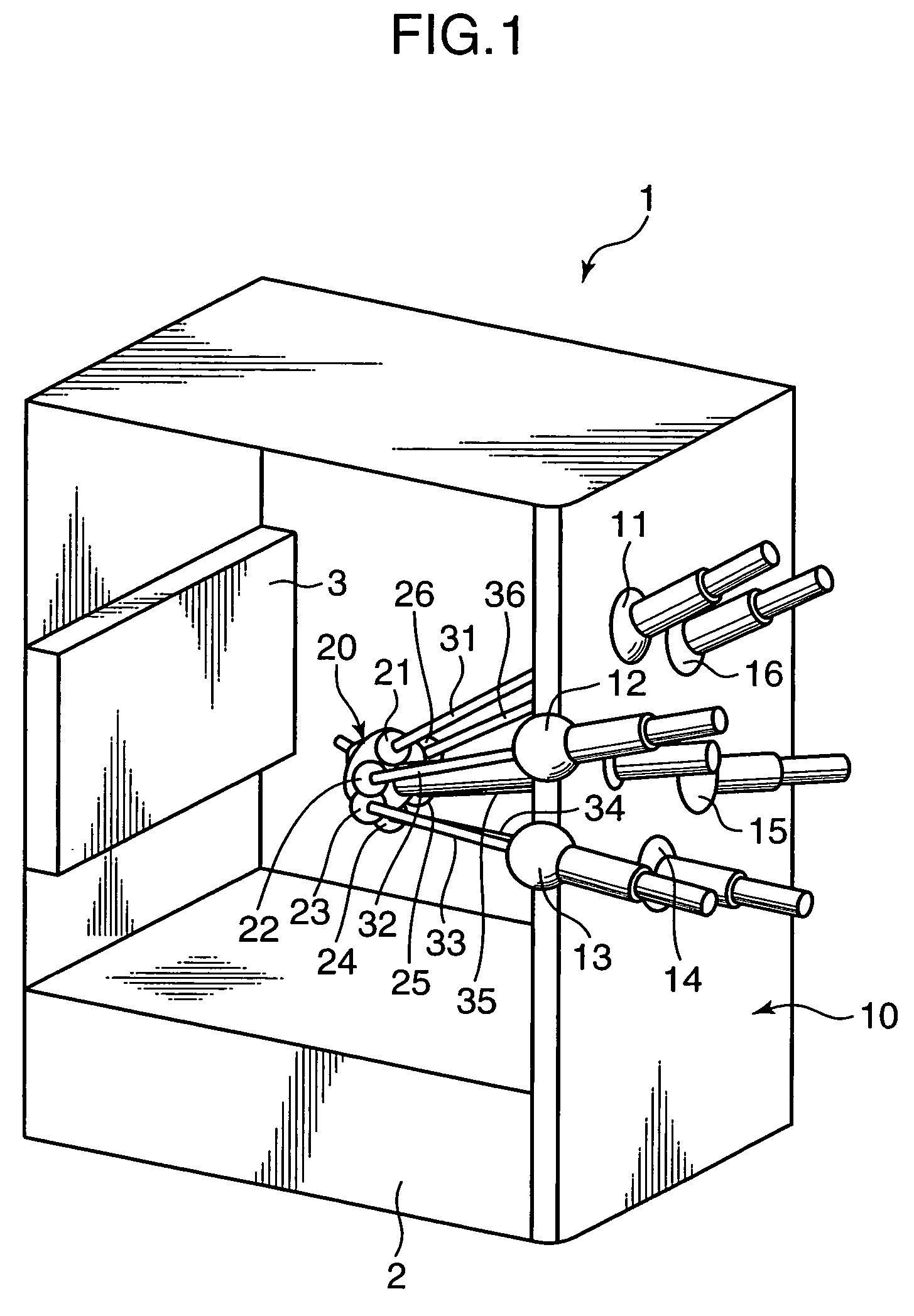
[0029]Referring to FIG. 1 showing a mechanical configuration of the parallel kinematic machine embodying the invention, the parallel kinematic machine 1 (hereinafter, referred to as “machine”) includes a base 10 supported by a support platform 2 and an end effecter 20. Six joints 11 to 16 are provided in the base 10, and six joints 21 to 26 are provided in the end effecter 20. Six struts 31 to 36 are connected to the joints 11 to 16, and to the six joints ...


PUM

PropertyMeasurementUnit
degrees of freedomaaaaaaaaaa
orientation angleaaaaaaaaaa
diameteraaaaaaaaaa

Abstract

A calibration method is provided for calibrating a parallel kinematic mechanism that has an end effecter. The method includes setting an adjustment tool attached to the end effecter in predetermined postures in a reference coordinate system by taking coordinates of the posture of the adjustment tool each time the adjustment tool is placed in the posture and recording coordinates of driver shafts manipulated by a numerical control device in accordance with the inverse kinematics each time the adjustment tool is placed in the posture. The method continues by calculating kinematic parameters necessary for the kinematics of the parallel kinematic mechanism based on the taken coordinates of the postures of the driver shafts and the recorded coordinates of the driver shafts. Accordingly, it is possible to obtain accurate posture information of the end effecter and relative coordinates of the driver shafts.

Description

BACKGROUND OF THE INVENTION[0001]1. Field of the Invention[0002]The present invention relates to a calibration technology in a parallel kinematic mechanism which requires no measurements after posturing.[0003]2. Description of the Related Art[0004]A parallel kinematic mechanism which is provided with a base and an end effecter connected in parallel by a plurality of driver shafts has higher rigidity and accuracy in posturing than a mechanism which is provided with a cantilever. The Stewart platform is a typical example of the parallel kinematic mechanisms. The Stewart platform has straight driver shafts or struts which are expanded or contracted to control the posture (including a position and an orientation) of the end effecter. For the highly accurate posturing, however, it is necessary to calculate accurate kinematic parameters such as the length of a strut, coordinates of a joint connecting a strut and a base, and a joint connecting a strut and the end effecter. This operation i...

Claims


Application Information

Patent Timeline
Patent Type & Authority Patents(United States)
IPC IPC(8): B25J9/16G01B5/00G05B19/402
CPCB23Q1/5462B23Q17/22Y10T409/309576Y10T409/307672G06F15/16
Inventor NISHIBASHI, NOBUTAKAYAGI, KAZUAKI
Owner SHINNIPPON KOKI
Why Eureka
Try Eureka