Solar thermal electric cells and panels

a solar thermal and electric cell technology, applied in the field of solar thermal electric cells and panels, can solve the problem of quite high production cos

Inactive Publication Date: 2004-07-08
LUONG HUAN VINH +2
View PDF4 Cites 27 Cited by
  • Summary
  • Abstract
  • Description
  • Claims
  • Application Information

AI Technical Summary

Problems solved by technology

For these reasons, the production cost is quite high.

Method used


Image

  • Solar thermal electric cells and panels
  • Solar thermal electric cells and panels
  • Solar thermal electric cells and panels

Examples


Embodiment Construction

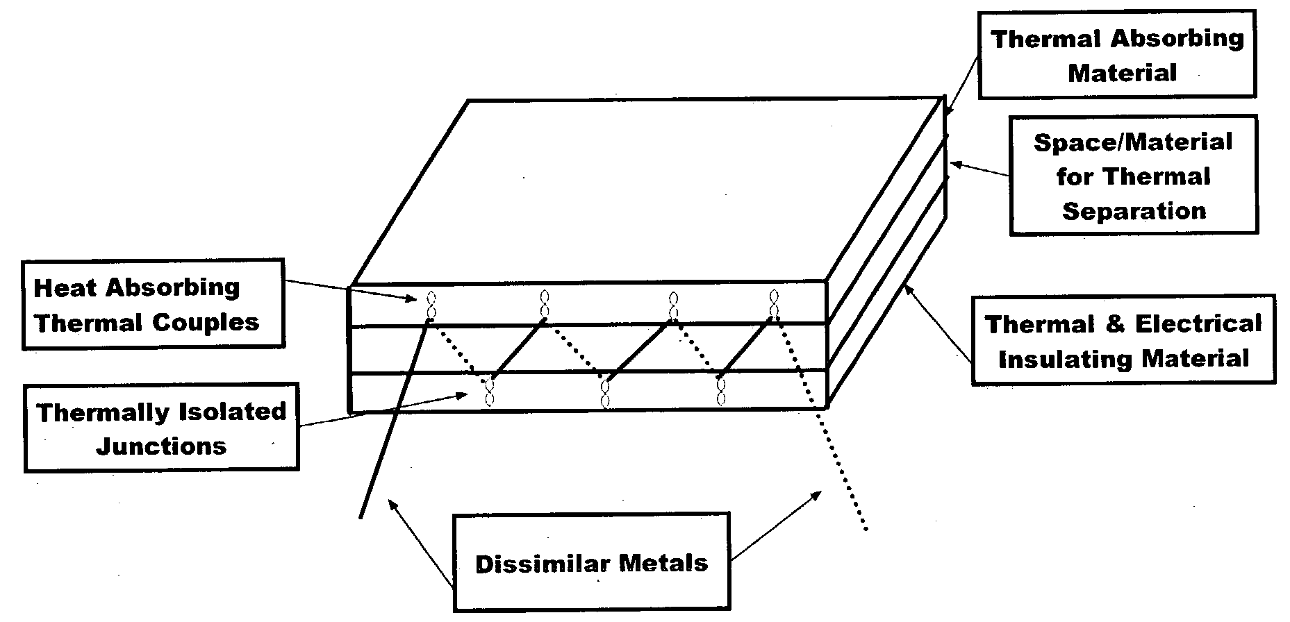
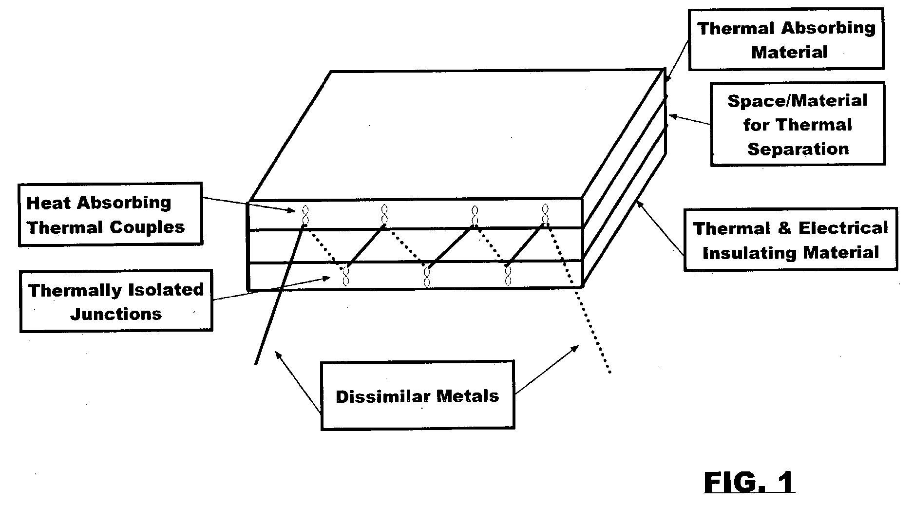
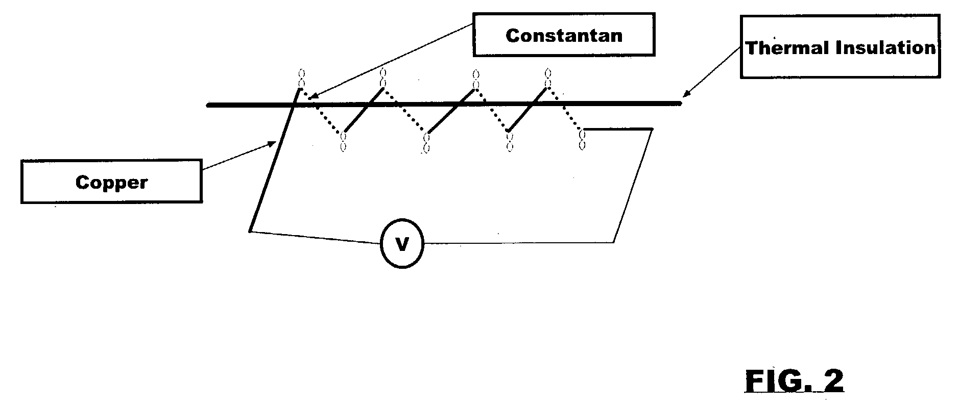
[0004] Our invention utilizes the concept of the Seebeck effect, which was discovered by Thomas Seebeck in 1821. This effect states that when two dissimilar metals are brought together at two ends, and if one end is heated, current will flow in the circuit. This idea of producing electricity relies on the fact that the two ends of the metal pair joints are at different temperatures.

[0005] For the last two decades, thermal absorbing material development has been advancing in a rapid pace. As a result, we now can use these materials to keep one side of the Seebeck circuit at a high temperature, while maintaining one side at a lower temperature. This means it is now possible to apply the Seebeck effect to construct solar thermal electric cells and panels that do not requires semiconductor technology.

[0006] In our invention, the solar electric cell consists of two dissimilar metals in the form of wire, strip, mesh or any other shape, joined together in series and parallel fashions. A la...


PUM


Abstract

This invention relates mainly to a method for constructing low cost solar electric cells and panels. The Seeback effect is used in the conversion of solar heat to electricity. Temperature differential between two sides of the solar panel is achieved with the use of thermal absorbing materials and insulating materials. Dissimilar metal wires or strips are used in series and parallel to obtain the appropriate voltage and current.

Description

TECHNICAL FIELD OF INVENTION[0001] The present invention relates generally to solar electric cell technology. The invention relates in particular to solar electric cells and panels that can convert solar heat to electricity.BACKGROUND OF INVENTION[0002] Solar energy has two advantages over conventional energy; it is clean and the resource is boundless. The efficiency of solar electric technology is rapidly approaching the 30% mark, the so-called upper limit. As a result, it is clear that solar electric is a very attractive technology. Currently, solar electric cells and panels are being manufactured via semiconductor technology, which requires the use of high temperature processes (400-1400 degrees C.), and high vacuum systems. For these reasons, the production cost is quite high.[0003] We are taking an alternative approach to harnessing solar energy, by making affordable solar electric cells and panels that can be produced easily. Our invention deals with low cost solar cells and p...

Claims


Application Information

Patent Timeline
Patent Type & Authority Applications(United States)
IPC IPC(8): H01L35/32
CPCH01L35/32H10N10/17
Inventor LUONG, HUAN VINHLIN, HSING KUANGMUELLER, GEORGE STEPHEN
Owner LUONG HUAN VINH
Why Eureka
Try Eureka