Instrumentation for a downhole deployment valve

a technology of deployment valve and instrumentation, which is applied in the direction of instruments, wellbore/well accessories, survey, etc., can solve the problems of inability to know the pressure differential between the flapper and the instrumentation, the tool strings are too long for use with a lubricator, and the mud and damage to formations

Inactive Publication Date: 2004-07-08
WEATHERFORD TECH HLDG LLC
View PDF99 Cites 84 Cited by
  • Summary
  • Abstract
  • Description
  • Claims
  • Application Information

AI Technical Summary

Problems solved by technology

While drilling with weighted fluid provides a safe way to operate, there are disadvantages, like the expense of the mud and the damage to formations if the column of mud becomes so heavy that the mud enters the formations adjacent the wellbore.
Underbalanced drilling involves the formation of a wellbore in a state wherein any wellbore fluid provides a pressure lower than the natural pressure of formation fluids.
In these instances, the fluid is typically a gas, like nitrogen and its purpose is limited to carrying out drilling chips produced by a rotating drill bit.
As the formation and completion of an underbalanced or near underbalanced well continues, it is often necessary to insert a string of tools into the wellbore that cannot be inserted through a rotating drilling head or blow out preventer due to their shape and relatively large outer diameter.
While lubricators are effective in controlling pressure, some strings of tools are too long for use with a lubricator.
Presently there is no instrumentation to know a pressure differential across the flapper when it is in the closed position.
Similarly when the hydraulic pressure is applied to the mandrel to move it one way or the other, there is no way to know the position of the mandrel at any time during that operation.
Coupling the seismic sensor to the formation from production tubing includes distance and therefore requires complicated maneuvers and equipment to accomplish the task.
In addition to problems associated with the operation of DDVs, many prior art downhole measurement systems lack reliable data communication to and from control units located on the surface.
For example, conventional measurement while drilling (MWD) tools utilize mud pulse, which works fine with incompressible drilling fluids such as a water-based or an oil-based mud, but they do not work when gasified fluids or gases are used in underbalanced drilling.
However, EM telemetry suffers from signal attenuation as it travels through layers of different types of formations.
In particular salt domes tend to completely attenuate or moderate the signal.
However, both of these techniques have their own problems and complexities.
Currently, there is no available means to cost efficiently relay signals from a point within the well to the surface through a traditional control line.
While too much expansion is bad for both the ESS and the well, too little expansion does not provide support to the wellbore wall.

Method used


Image

  • Instrumentation for a downhole deployment valve
  • Instrumentation for a downhole deployment valve
  • Instrumentation for a downhole deployment valve

Examples


Embodiment Construction

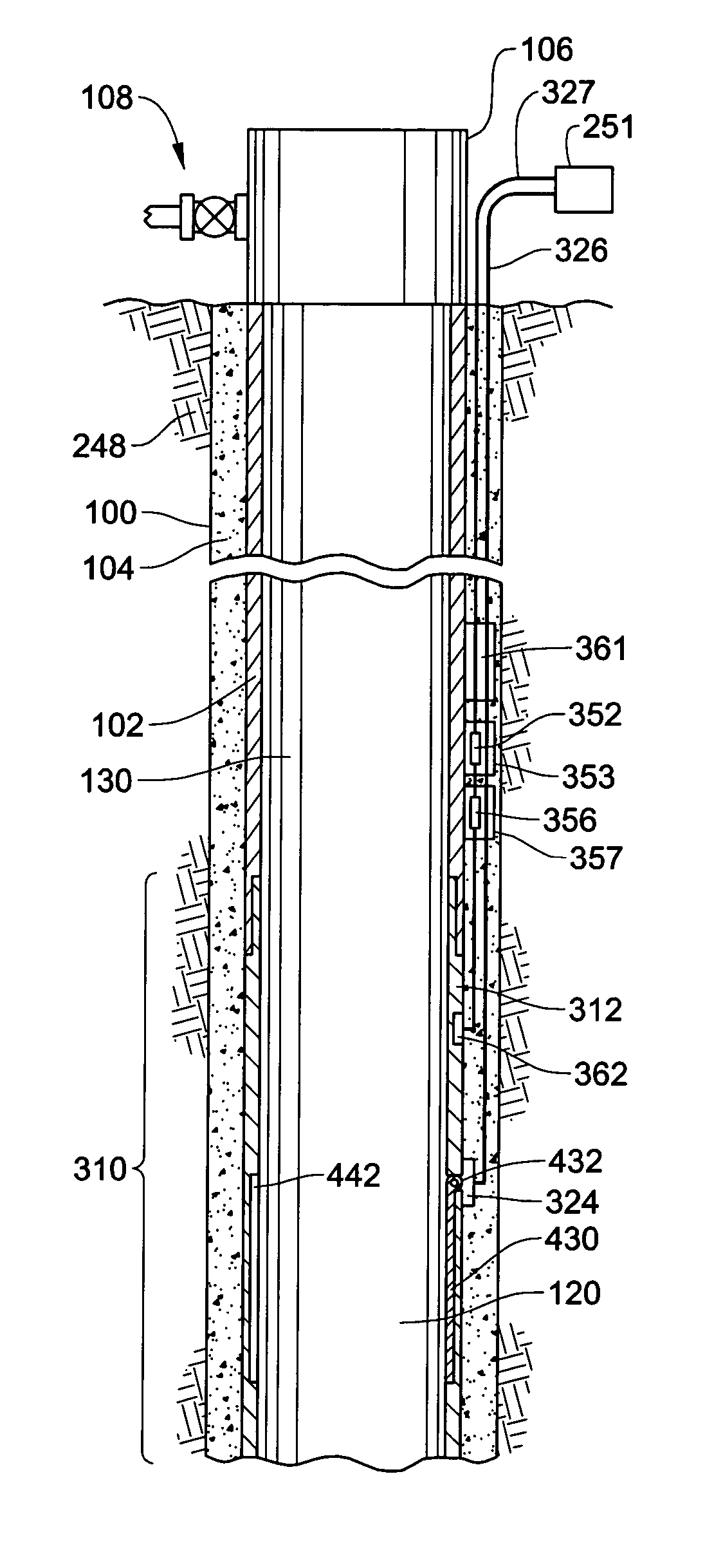
[0044] Placement of one or more seismic sensors on the outside of a casing string reduces the inherent fluid interference and casing string interference with signals which occurs when the seismic sensors are present within the casing string on the production tubing and also increases the proximity of the seismic sensors to the formation, thus allowing provision of more accurate signals and the simplifying of coupling means of the seismic sensors to the formation. Substantially accurate real time measurements of seismic conditions and other parameters are thus advantageously possible during all wellbore operations with the present invention. With the present invention, permanent seismic monitoring upon placement of the casing string within the wellbore allows for accurate measurements of seismic conditions before and after production tubing is inserted into the wellbore.

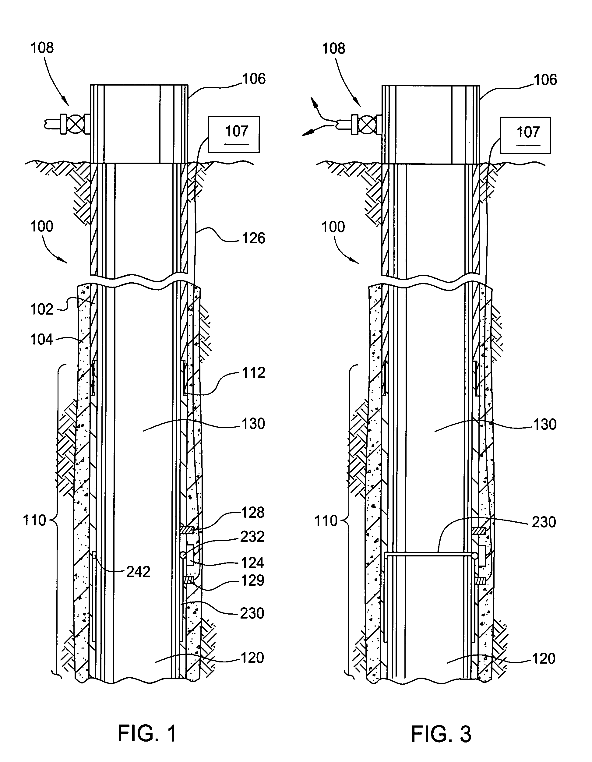
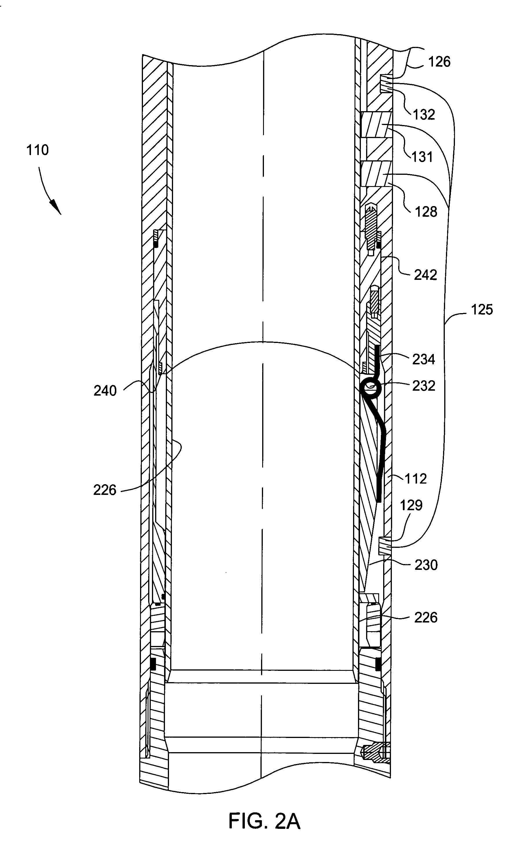
[0045] Sensors with Downhole Deployment Valves

[0046] FIG. 1 is a section view of a wellbore 100 with a casing strin...


PUM


Abstract

The present generally relates to apparatus and methods for instrumentation associated with a downhole deployment valve or a separate instrumentation sub. In one aspect, a DDV in a casing string is closed in order to isolate an upper section of a wellbore from a lower section. Thereafter, a pressure differential above and below the closed valve is measured by downhole instrumentation to facilitate the opening of the valve. In another aspect, the instrumentation in the DDV includes sensors placed above and below a flapper portion of the valve. The pressure differential is communicated to the surface of the well for use in determining what amount of pressurization is needed in the upper portion to safely and effectively open the valve. Additionally, instrumentation associated with the DDV can include pressure, temperature, seismic, acoustic, and proximity sensors to facilitate the use of not only the DDV but also telemetry tools.

Description

[0001] This application is a continuation-in-part of co-pending U.S. patent application Ser. No. 10 / 288,229, filed Nov. 5, 2002, which is herein incorporated by reference in its entirety.[0002] This application is related to co-pending U.S. patent application Ser. No. ______ having Attorney Docket Number WEAT / 0438, filed on the same day as the current application, entitled "Permanent Downhole Deployment of Optical Sensors", which is herein incorporated by reference in its entirety.[0003] 1. Field of the Invention[0004] The present invention generally relates to methods and apparatus for use in oil and gas wellbores. More particularly, the invention relates to using instrumentation to monitor downhole conditions within wellbores. More particularly, the invention relates to methods and apparatus for controlling the use of valves and other automated downhole tools through the use of instrumentation that can additionally be used as a relay to the surface. More particularly still, the in...

Claims


Application Information

Patent Timeline
Patent Type & Authority Applications(United States)
IPC IPC(8): E21B21/00E21B21/08E21B21/10E21B34/00E21B34/06E21B34/10E21B47/10E21B47/12
CPCE21B21/08E21B34/06E21B34/101E21B2034/005E21B47/122E21B2021/006E21B47/10E21B21/085E21B2200/05E21B47/13
Inventor HOSIE, DAVID G.GRAYSON, MICHAEL BRIANBANSAL, R.K.BOSTICK, F.X. III
Owner WEATHERFORD TECH HLDG LLC
Why Eureka
Try Eureka