Lighting device and use thereof

a technology of lighting devices and light sources, applied in the field of lighting devices, can solve problems such as reducing the quality of lighting, and achieve the effect of reducing the drawback

Inactive Publication Date: 2004-07-08
ALM
View PDF11 Cites 64 Cited by
  • Summary
  • Abstract
  • Description
  • Claims
  • Application Information

AI Technical Summary

Benefits of technology

0005] An object of the present invention is to mitigate that dr

Problems solved by technology

When an obstacle, such as a surgeon's head, intercepts the path of light from the light source to the li

Method used


Image

  • Lighting device and use thereof
  • Lighting device and use thereof
  • Lighting device and use thereof

Examples


Embodiment Construction

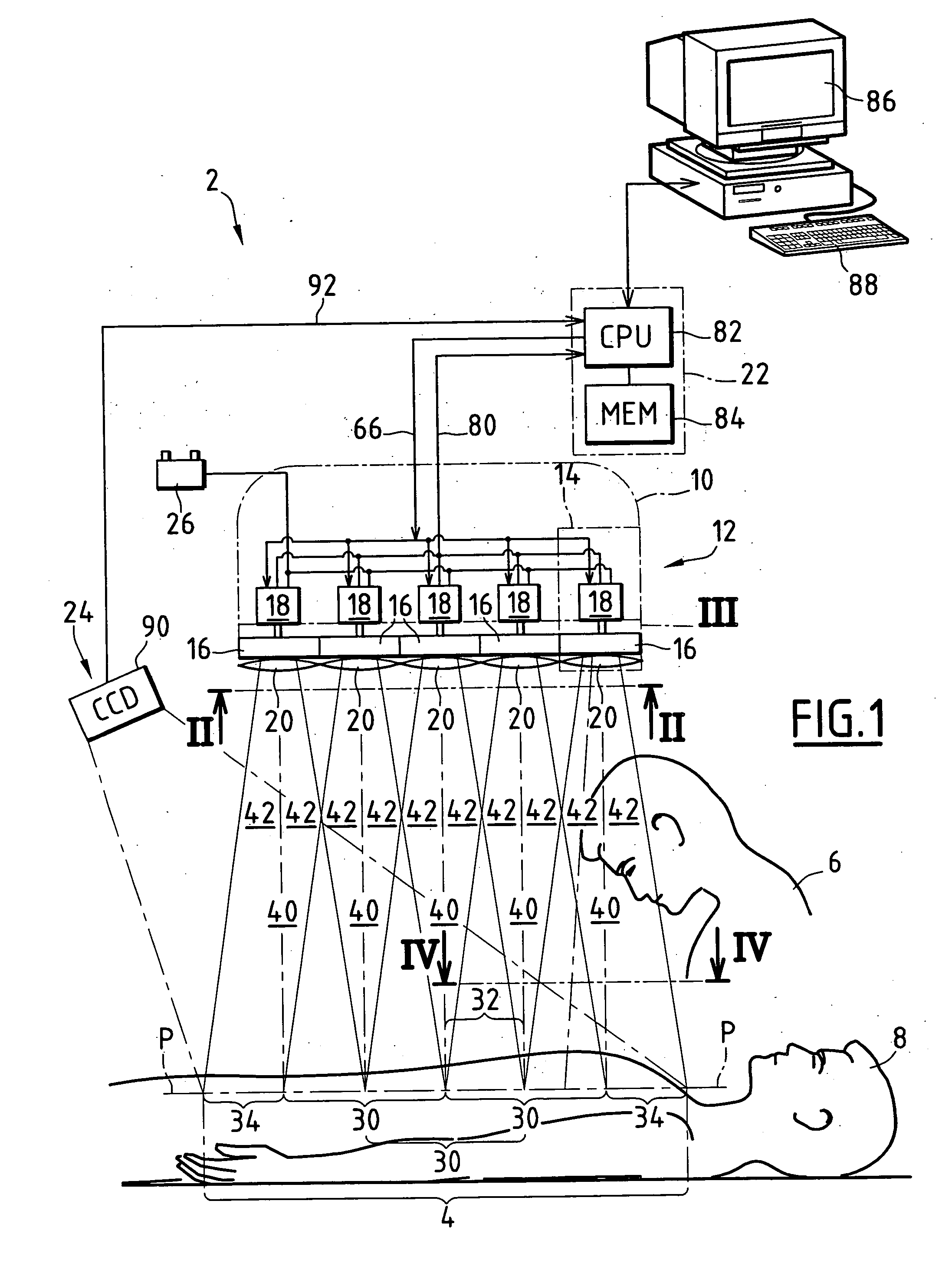
[0025] FIG. 1 shows a lighting installation of the invention, given overall reference 2.

[0026] The installation is designed to light a lighted field 4 extending in a horizontal lighted plane P-P. Specifically, the lighted field 4 is the field in which a doctor 6 is taking action on a patient 8 in an operating theater.

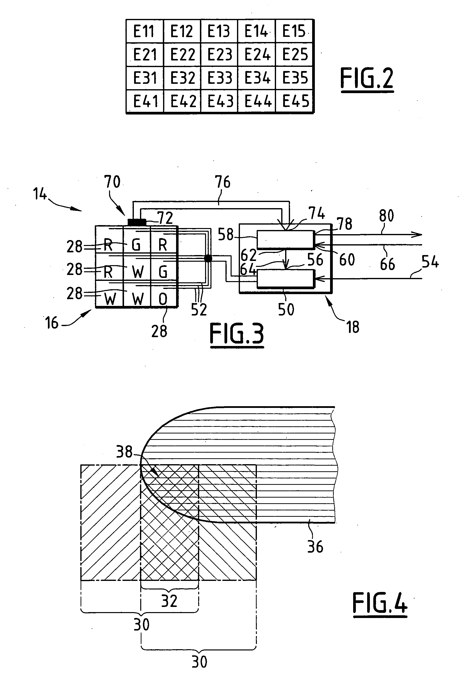
[0027] The installation 2 comprises a housing 10 containing a light source 12 constituted by a plurality of lighting elements 14. In the present case, the installation 12 comprises a matrix of twenty lighting elements 14 arranged in five columns of four rows each, as shown in FIG. 2. The five lighting elements 14 in the first row can be seen in FIG. 1.

[0028] Each lighting element 14 comprises a lighting module 16, a control unit 18 associated with the lighting module 16, and optical elements 20.

[0029] The installation 2 also comprises a central unit 22, means 24 for detecting an obstacle, and a source 26 of electricity.

[0030] As shown in FIG. 3, each lighting module 16 ...


PUM


Abstract

The lighting device for lighting a lighted field comprises a light source having first and second lighting modules. The lighting modules are adapted to light lighted domains of the lighted field. The lighted domains form an overlap zone, and each lighting module defines an overlap volume. The device includes detector means adapted to detect a zone of reduced lighting in the overlap zone, and control means adapted to increase the light flux from said second lighting module when the detector means detect a zone of reduced lighting. The invention is applicable to lighting devices used in operating theaters.

Description

[0001] The present invention relates to a lighting device for lighting a lighted field, in particular an operative field for a doctor, the device being of the type comprising a light source with first and second lighting modules, the lighting modules being adapted to light respective first and second lighted domains of the lighted field, said lighted domains overlapping at least in part so as to form an overlap zone, and each lighting module defining an overlap volume extending between the overlap zone and the surface of the light-emitting module that emits light towards the overlap zone.[0002] It applies in particular to devices for lighting operative fields in surgical operating theaters.[0003] Lighting devices in operating theaters are known. Such devices comprise a light source whose light beam is directed towards the operative field.[0004] When an obstacle, such as a surgeon's head, intercepts the path of light from the light source to the lighted field, a shadow is cast, there...

Claims


Application Information

Patent Timeline
IPC IPC(8): A61B19/00F21S2/00B60Q11/00F21S8/00F21V11/00F21V14/00F21V23/04F21W131/205F21Y101/02G01J1/32H05B37/02H05B39/04
CPCA61B19/5202F21V23/04F21V23/0442F21W2131/205F21V23/0457F21Y2113/005G01J1/32H05B37/02H05B39/042F21Y2101/02A61B90/30F21Y2115/10F21Y2113/13F21V23/0478H05B47/10Y02B20/00H05B47/165
Inventor THIBAUD, PHILIPPEMONNOT, JEROMEBOUILLHOL, SEBASTIENFICHOT, YVES
Owner ALM
Why Eureka
Try Eureka