Eureka AIR delivers breakthrough ideas for toughest innovation challenges, trusted by R&D personnel around the world.

Image displaying system, image displaying device, image data outputting device, image displaying method, image displaying program, and image data outputting program

a technology of image data and display system, which is applied in the field of conventional image display system, can solve the problems of network low throughput, repeating transmission, and failing to achieve adequate transmission,

Active Publication Date: 2004-07-08
SEIKO EPSON CORP
View PDF7 Cites 58 Cited by
  • Summary
  • Abstract
  • Description
  • Claims
  • Application Information

AI Technical Summary

Benefits of technology

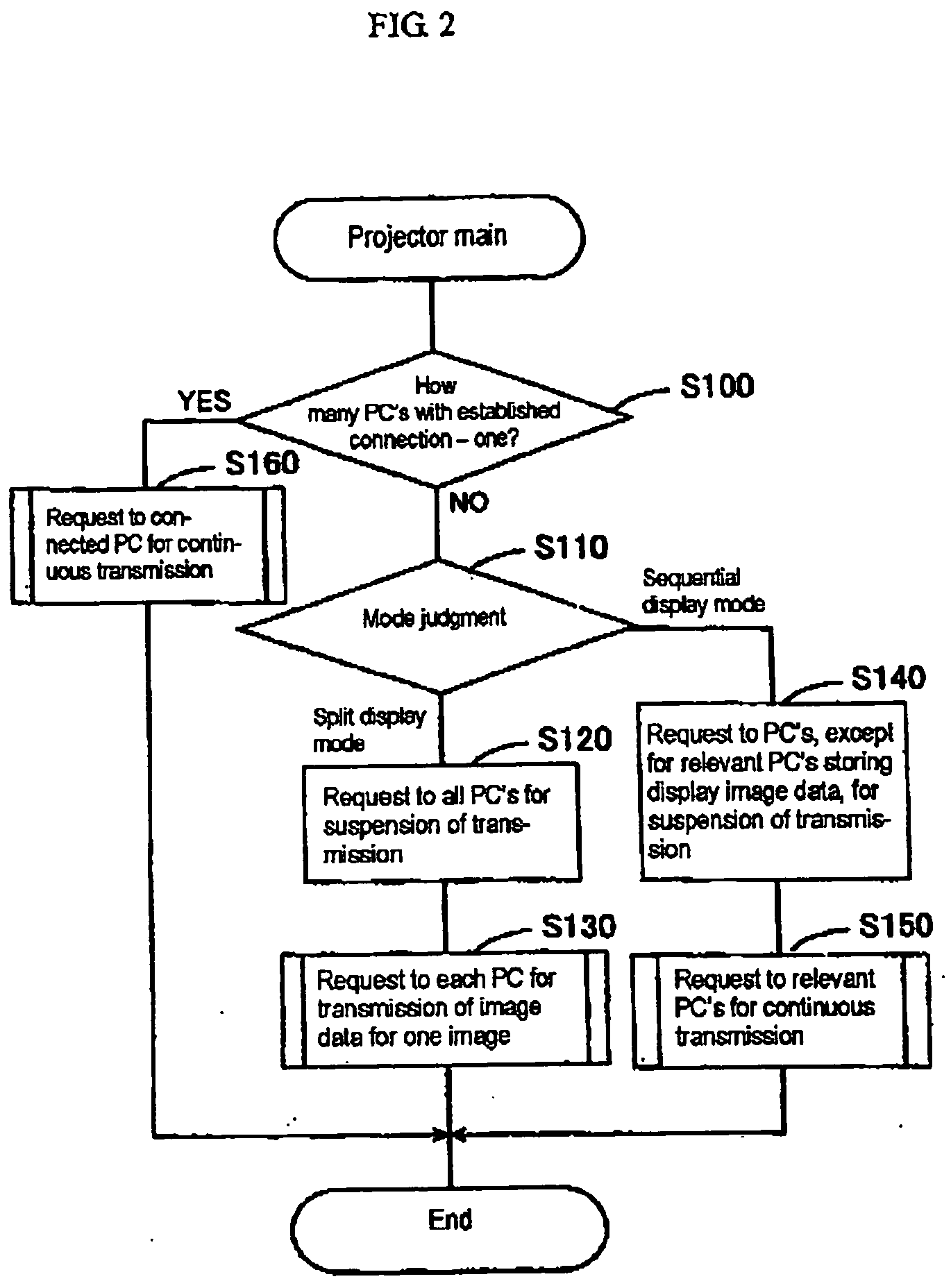
[0015] According to the present invention, acquisition of images from a plurality of terminals is accomplished in such a way that the image displaying device acquires image data from a specific terminal and then (after it has acquired image data) it acquires image data from another terminal. Therefore, if images in split sections are switched one by one, it is possible to prohibit transmission from terminals other then that which outputs image data for the image which has been switched. This permits the image displaying device to acquire necessary data rapidly. In this way it is possible to prevent the transmission of image data for the image which is not switched. In other words, there is no possibility that unnecessary data is transmitted over the network.
[0016] The sequential display mode is one which displays on a single screen the image based on image data which has been output from a plurality of terminals and which switches the image as required. This arrangement realizes presentation with images which have been output from a plurality of terminals. In this case, too, the image displaying device only acquires the image data for images being displayed and hence the image data for images not being displayed is not transmitted over the network. Therefore, there is no possibility that unnecessary data is transmitted over the network. This reduces the network load and permits speedy acquisition of necessary data. Incidentally, in either mode, the switching of images may be accomplished by means of a button (on the image displaying device) or a remote controller.
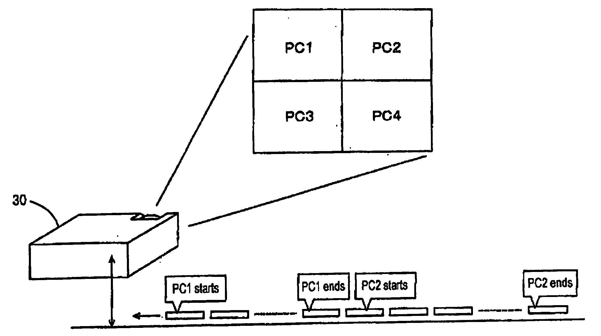
[0017] A desirable split display mode may be constructed such that the image displaying device sequentially acquires image data for the images to be displayed on the split sections. In this case, the terminals (or the abovementioned specific terminals) which output image data are sequentially switched without suspending the output of image data. In other words, as one terminal completes the output of image data, the image displaying device instructs that terminal to suspend transmission and instructs other terminals not to perform transmission. It is also possible to instruct a now specific terminal to start transmission instead of instructing to suspend transmission. In this way it is possible to limit the number of terminals which send data over the network and to permit the image displaying device to acquire image data for each image to be displayed on the split section while keeping the network load low.

Problems solved by technology

The conventional image displaying system mentioned above has the disadvantage of being low in throughput on account of the network.
In other words, the network is limited in the maximum transmission rate, and this poses a problem with transmission.
That is if a plurality of terminals happen to transmit image data simultaneously, one of them may fail in adequate transmission or have to repeat transmission on account of congestion.
Of course, the transmission of data is postponed if the amount of image data exceeds the capacity of the buffer in the image displaying device.

Method used


Image

  • Image displaying system, image displaying device, image data outputting device, image displaying method, image displaying program, and image data outputting program
  • Image displaying system, image displaying device, image data outputting device, image displaying method, image displaying program, and image data outputting program
  • Image displaying system, image displaying device, image data outputting device, image displaying method, image displaying program, and image data outputting program

Examples


Embodiment Construction

[0026] The embodiment of the present invention will be described in the order shown below.

[0027] (1) Construction of the image displaying system

[0028] (2) Processing by the projector

[0029] (3) Processing by each terminal

[0030] (4) Action of the image displaying system

[0031] (5) Other embodiments

[0032] (1) Construction of the Image Displaying System

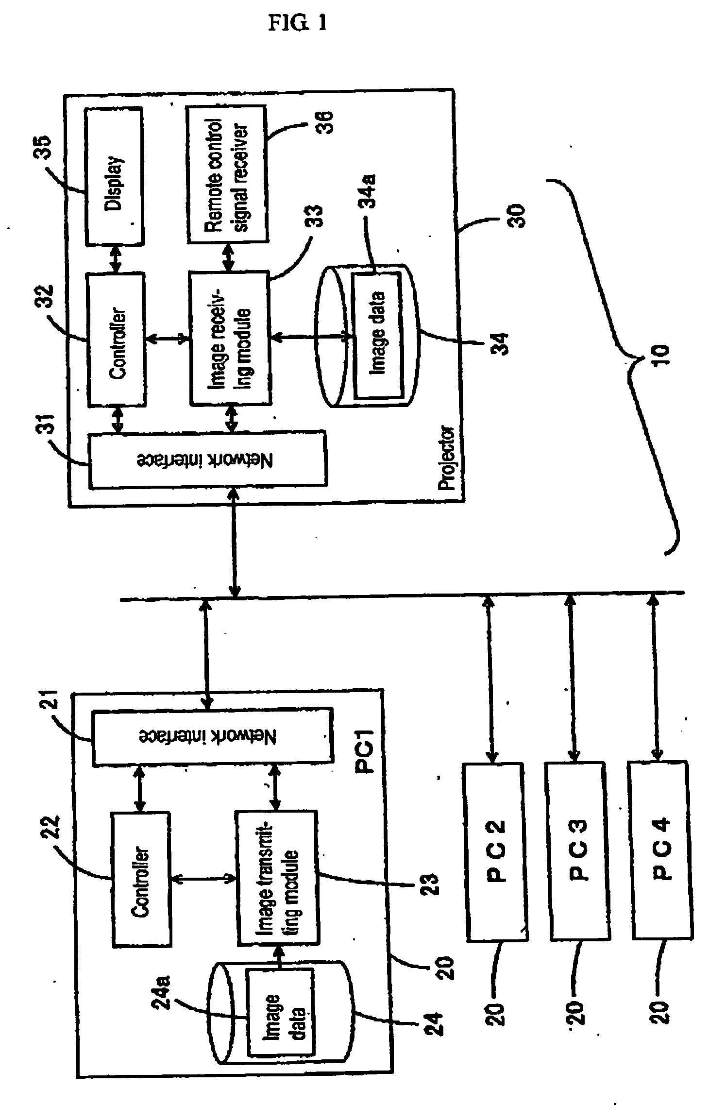
[0033] FIG. 1 is a diagram showing the construction of the image displaying system. In this figure, there is shown the image displaying system 10, which consists of a plurality of computers PC 20 and the projector 30. The projector 30 acquires the image data which has been output from each computer PC 20 and then projects an image for display according to the thus acquired image data. In this embodiment, the computers PC 20 and the projector 30 communicate with each other through the UTP cable for LAN.

[0034] In addition, the computers PC 20 and the projector 30 communicate with each other by means of TCP protocol. The computers PC 20 and t...


PUM


Abstract

A system consisting of a plurality of terminals storing image data and an image displaying device which are connected with each other through a network capable of two-way communication has the disadvantage of decreasing in throughput on account of slow image data transfer over the network. According to the present invention, the image displaying device performs two-way communications with each of the terminals by a communication means at the display device side. Also, the image displaying device acquires image data from a relevant terminal while instructing other terminals to suspend transmission by the image data acquisition controlling means, thereby suspending transmission of image data. The image displaying device displays images by the image displaying means based on the thus acquired image data.

Description

[0001] 1. Field of the Invention[0002] The present invention relates to an image displaying system, image displaying device, image data outputting device, image displaying method, image displaying program, and image data outputting program.[0003] 2. Description of the Prior Art[0004] The image displaying system of conventional type consists of an image displaying device and a plurality of terminals connected thereto through a network so that the former displays images in response to image data transmitted from the latter. (See Japanese Patent Laid-open No. 2001-358919, for example.) In such a system, transmission of image data from the image data sources to the image displaying device is efficiently accomplished by giving an identifier to each image data source and allocating the storage areas in the image displaying device in correspondence with the identifier. Thus, the image data transmitted from each image data source is stored in each of the allocated areas This arrangement per...

Claims


Application Information

Patent Timeline
IPC IPC(8): G06F13/00G06F15/16G09G5/00
CPCH04L12/2838H04L2012/2849G09G5/006G06F3/1438G09G5/001G09G5/14
Inventor SATO, MINORUKUBOTA, SHINJINOMIZO, TOMOHIRO
Owner SEIKO EPSON CORP
Why Eureka
Eureka Blog
Learn More