Lighting module for a vehicle headlight

a technology for headlights and modules, applied in fixed installations, lighting and heating apparatus, instruments, etc., can solve problems such as affecting a significant part of the light flux emitted by light sources is dissipated in the rear face of masks, so as to avoid the use of masks, reduce the loss of light flux, and clean cut off

Active Publication Date: 2004-07-08
VALEO VISION SA
View PDF3 Cites 69 Cited by
  • Summary
  • Abstract
  • Description
  • Claims
  • Application Information

AI Technical Summary

Benefits of technology

0012] The present invention aims to provide a lighting module for a vehicle headlight which produces a light beam of the cut-off type that gives a clean cut-off, espe

Problems solved by technology

Such a solution does however have certain difficulties.
Thus, one disadvantage of this type of headlight is that a significant part of the light flux emitted by the light source is dissipated in the rear face of the mask.
But again, this solution gives rise to some problems.
In this connection, where the light source is a diode, it is very difficult to produce a full cut-off.
This is because the image of the virtual source corresponding to the diode is generally r

Method used


Image

  • Lighting module for a vehicle headlight
  • Lighting module for a vehicle headlight
  • Lighting module for a vehicle headlight

Examples


first embodiment

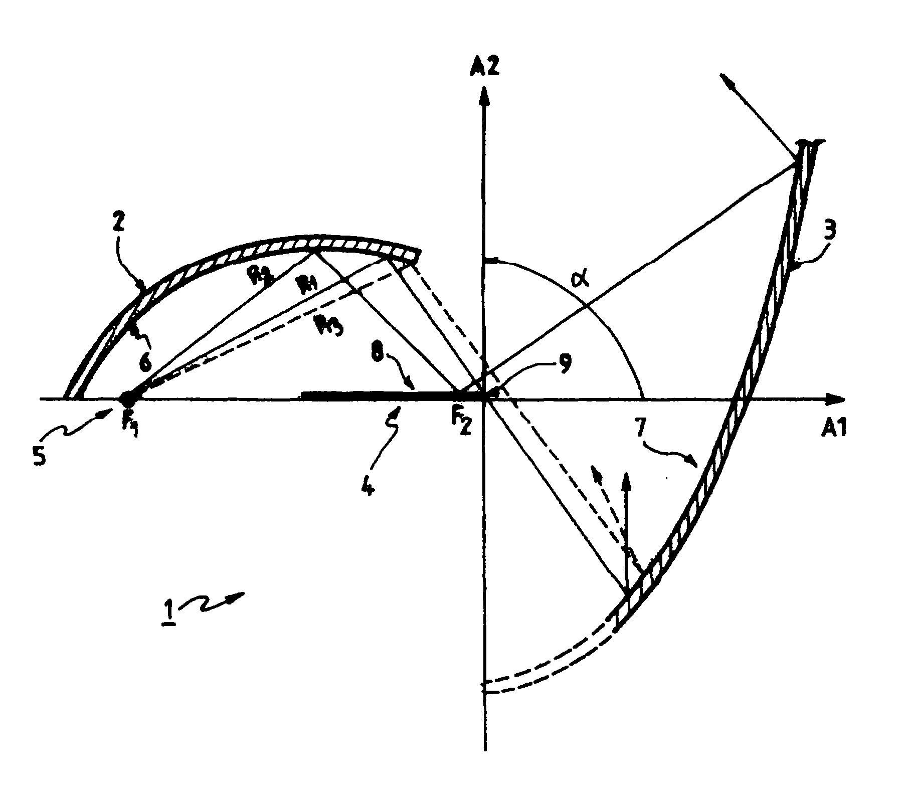
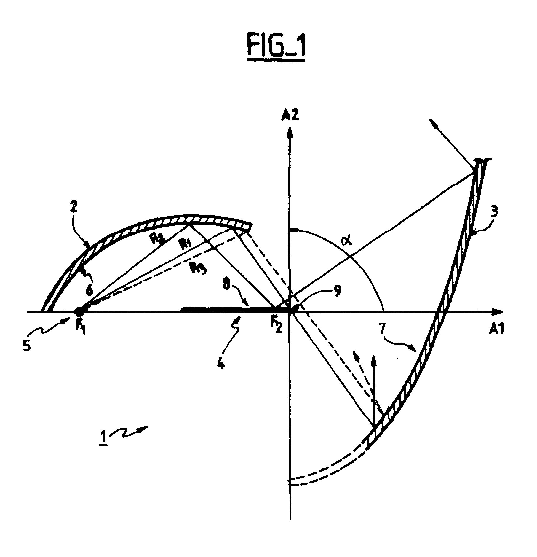
[0057] In the invention, the reflective surface 7 is substantially parabolic in form, the axis of the parabola being the optical axis A2.

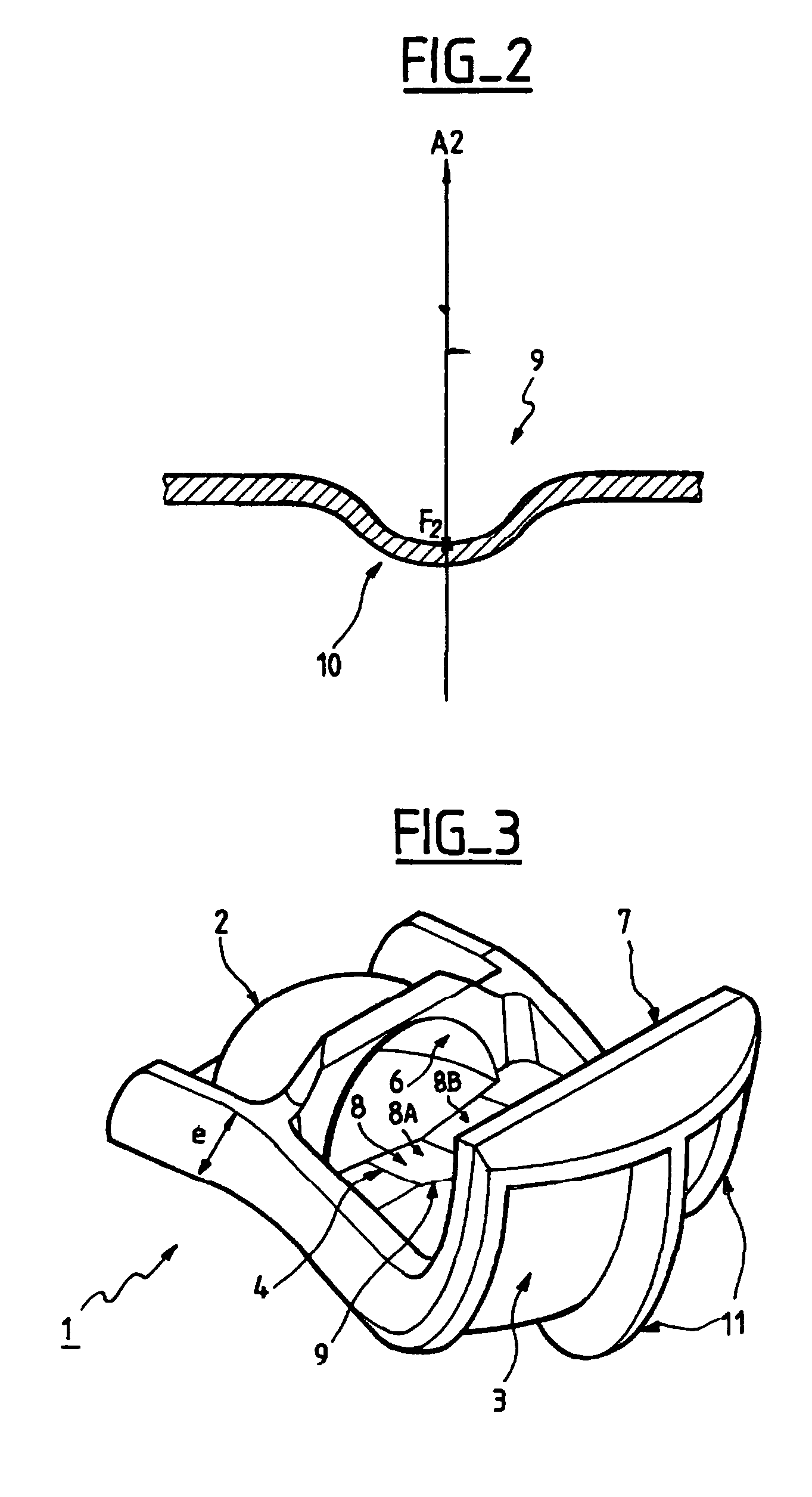
[0058] The third reflector 4 which may also be called the bender, is located between the first reflector 2 and second reflector 3, and has at least one reflective upper face 8 and a front terminal edge 9 which is called the cut-off edge.

[0059] The cut-off edge 9 is located in the vicinity of the second focus F2 of the first reflector 2.

[0060] It should be noted that the edge 9, as shown in FIG. 1, is straight, but the profile of the edge 9 may be modified in order to compensate for the field curvature of the substantially parabolic surface 7, as will be seen later herein.

[0061] The principle of operation of the lighting module 1 according to the invention is as follows.

[0062] In this connection, three light rays R1, R2 and R3, issued from the light source 5, will be considered for this purpose.

[0063] Since the light source 5 is arranged at the firs...

second embodiment

[0078] In a second embodiment, the material employed may be an injected metal of the aluminium type. This version avoids the need for the cooling means, because the properties of the metal can be used to evacuate the heat.

[0079] The invention is of course not limited to the embodiments just described. Thus, the method of manufacture described above makes use of a moulding process, but press-forming could also be used.

[0080] Similarly, the module of the invention has been described as being made in one piece, but it is just as much possible to make the various reflectors separately.

[0081] Moreover, the light source described is a photodiode, but it could also be another type of light source such as the free end of a fibre optic. It is also possible to make use of any type of lamp located at the first focus of a light collector of an elliptical type, the exit for the light being situated at the level of the second focus of the collector.


PUM


Abstract

The present invention is concerned with a lighting module for a vehicle headlight for giving a light beam of the cut-off type, particularly one which is adapted to use with light-emitting diodes. The module has a second reflector having a substantially elliptical surface for reflecting light rays and at least one light source arranged close to the first focus of the first reflector. The module also includes a second reflector for producing the cut-off or dipped output beam, the focus of this reflector being arranged close to the second focus of the first reflector. The module further includes a third reflector or bender, having a reflective top face and being situated between the first and second reflectors. This third reflector has a cut-off edge arranged close to the second focus of the first reflector, whereby to form the cut-off within the light beam. The light source is a light-emitting diode.

Description

[0001] The present invention relates to a lighting module for a vehicle headlight, for producing a light beam of the cut-off type for passing purposes, particularly but not exclusively adapted for use with light-emitting diodes.[0002] A cut-off light beam, also referred to as a passing beam, is to be understood to mean a light beam which has a directional limit, or cut-off, above which any light emitted is of low intensity.[0003] The functions of passing or dipped beam lights and foglights are examples of cut-off light beams conforming to current European legislation.[0004] Generally, the cut-off in an elliptical headlight is produced using a mask which is in the form of a vertical plate the profile of which is suitably adapted and which is interposed axially between the elliptical reflector and the convergent lens, and which is arranged close to the second focus of the reflector.[0005] The mask provides an occulting function for the light rays issued from the light source and refle...

Claims


Application Information

Patent Timeline
IPC IPC(8): F21S8/10F21V7/00F21V11/16F21V13/10F21V17/00F21W101/10F21Y101/02
CPCF21S48/1159F21S48/1388F21Y2101/02F21V13/10F21S48/145F21Y2115/10F21S41/321F21S41/43F21S41/365F21S41/148
Inventor ALBOU, PIERRE
Owner VALEO VISION SA
Why Eureka
Try Eureka