Balloon catheter with improved resistance to non-deflation

a balloon catheter and non-deflation technology, applied in balloon catheters, coatings, surgery, etc., can solve the problems of balloons subject to abnormally high radially inward pressure, difficult or impossible balloon deflation, and excessive traction

Active Publication Date: 2004-07-08
CR BARD INC
View PDF21 Cites 50 Cited by
  • Summary
  • Abstract
  • Description
  • Claims
  • Application Information

AI Technical Summary

Problems solved by technology

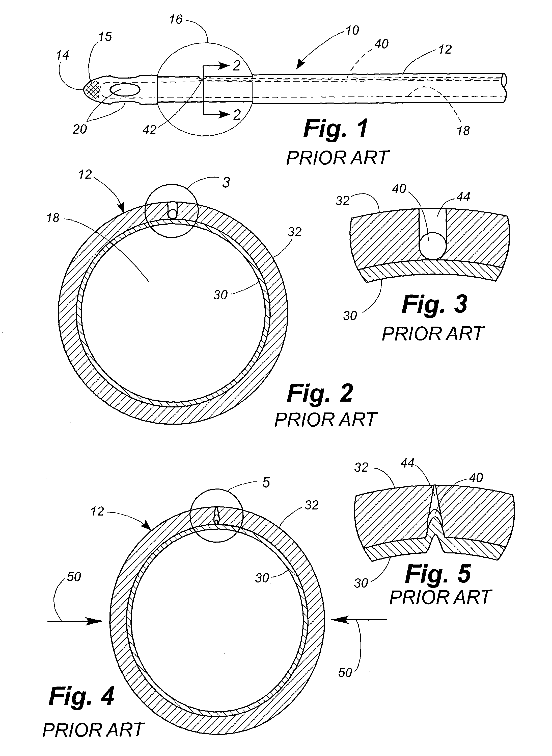
This radially inward pressure can result from any number of causes, including but not limited to under-inflation of the balloon, anatomical abnormality, excessive traction resulting from physician placement or patient movement, etc.
In addition, when a negative pressure is exerted by a syringe trying to aspirate fluid from the balloon 16, the effect can be to completely collapse the walls of the inflation lumen 40, making it difficult or impossible to deflate the balloon.
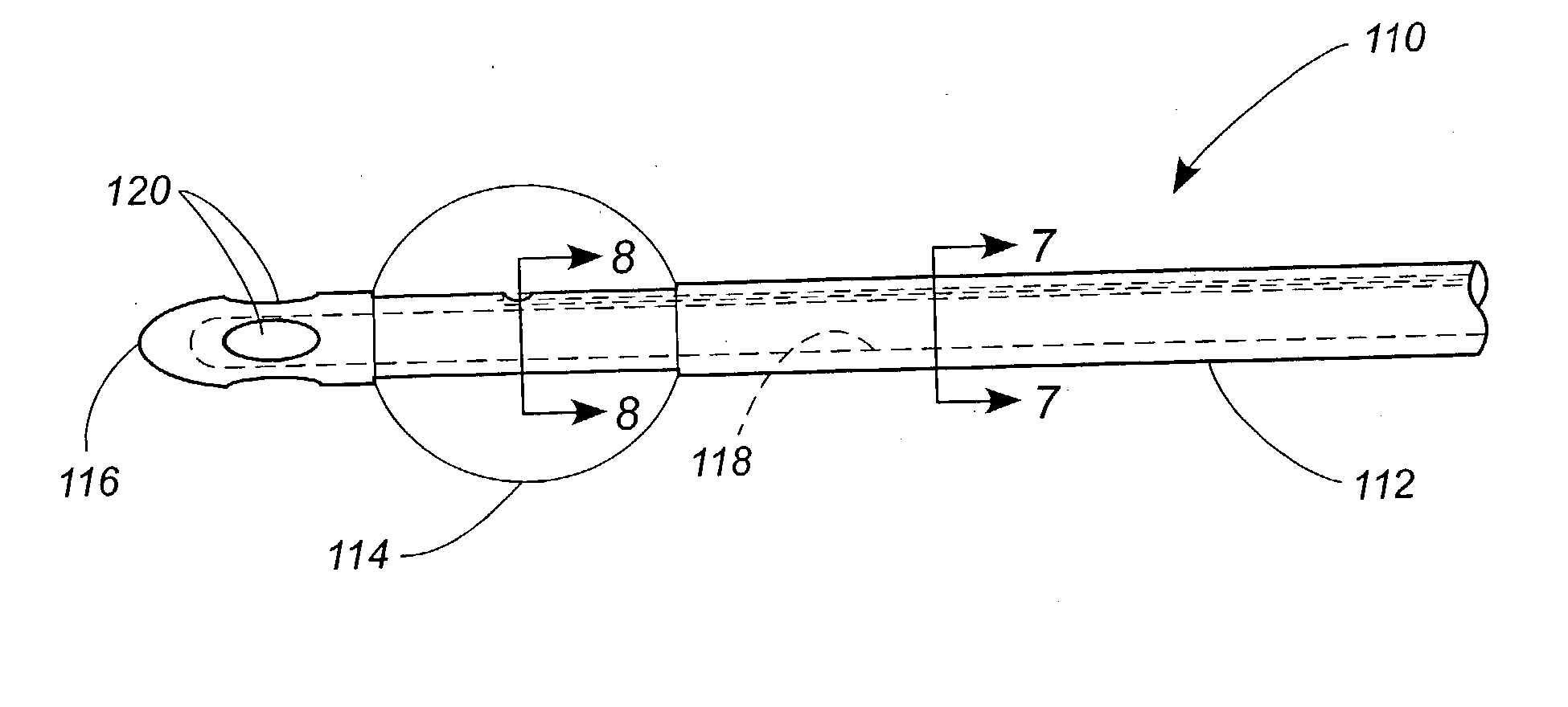
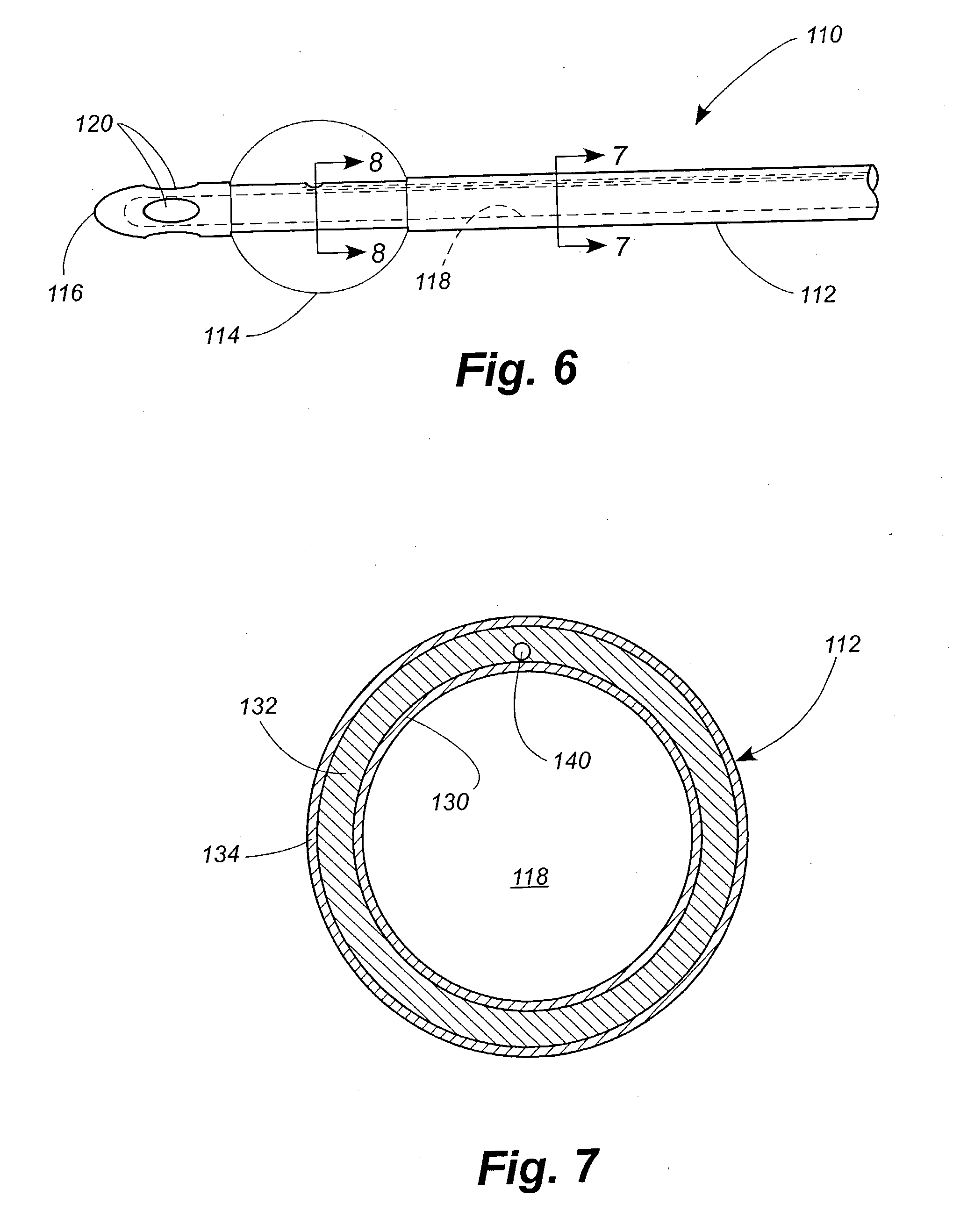
FIG. 10 is another cross-sectional view similar to FIG. 8, but in FIG. 10 the balloon is subject to abnormally high radially inward pressures.
As previously explained with respect to FIG. 4, such abnormally high radially inward pressure can result from any number of sources, including under-inflation of the balloon, anatomical abnormality, the physician pulling too hard on the catheter to seat the balloon in the neck of the bladder, etc.

Method used


Image

  • Balloon catheter with improved resistance to non-deflation
  • Balloon catheter with improved resistance to non-deflation
  • Balloon catheter with improved resistance to non-deflation

Examples


example 1

[0058] Example 1 as well as Comparative Examples 2 and 3 all had tip penetration values close to those of Comparative Example 1 despite the fact that only Comparative Example 1 included the reinforcement cap.

[0059] Only Example 1, having the material with the elevated Young's Modulus in the rubberize layer only, had Hand values similar to that of Comparative Example 1. Comparative Example 2, having elevated Young's Modulus in the build up layer, as well as Comparative Example 3, having elevated Young's Modulus in both the rubberize and build up layers, both had higher hand values, indicating a stiffer catheter. Example 1 also had Bending Modulus values only slightly higher than those of Comparative Example 1.

1TABLE 1 Tip Penetration, Hand and Bending Modulus Results. Bending Modulus Tip Penetration Hand (% Load Scale at (Pounds) (centimeters) 50 Degree Angularity) Example 1 21.77 11.31 26.8 Comparative 25.73 11.27 24.4 Example 1 Comparative 21.38 12.83 Example 2 Comparative 19.08 13...

example 2

[0062] COMPARATIVE EXAMPLE 4 was repeated, except that the latex catheter was prepared using materials having the same Young's Modulus values as the materials used in EXAMPLE 1. The patency of the inflation lumen was essentially retained at chamber pressures as high as 40 pounds per square inch, gage (psig).

example 3

[0063] The procedures of COMPARATIVE EXAMPLE 4 are repeated, except that the build up layer, not the rubberize layer, is prepared using materials having the same Young's Modulus values as the materials used on the rubberize layer in EXAMPLE 1. The rubberize layer has the Young's Modulus values of the rubberize layer in COMPARATIVE EXAMPLE 1. The drainage lumen of the resulting catheter does not retain its patency at elevated air pressures as well as the catheters of EXAMPLE 2.


PUM

PropertyMeasurementUnit
wet Young's Modulusaaaaaaaaaa

Abstract

Balloon catheters are disclosed that comprise a material that confers improved resistance to non-deflation. Balloon catheters are also disclosed that comprise a reduced drainage lumen diameter. In some embodiments the catheters achieve these characteristics without rendering the catheters undesirably stiff.

Description

[0001] The present invention relates generally to balloon catheters and relates more specifically to a balloon catheter that exhibits improved resistance to non-deflation.[0002] Balloon catheters are well known medical devices in which an inflatable member is located adjacent to the distal end medical devices of the catheter shaft and inflated once the catheter is positioned within the body of the patient to anchor the distal end. Such catheters comprise an elongated shaft defining a drainage lumen and an inflation lumen. The drainage lumen comprises a major portion of the cross-section of the catheter shaft and is closed at its distal end by a tip portion. Openings or ports distal to the balloon permit fluid to enter the drainage lumen. The proximal end of the drainage lumen is placed in fluid communication with a method of drainage such as a urinary drainage bag. In some embodiments, the communication is made through a drainage funnel located at the proximal end of the catheter th...

Claims


Application Information

Patent Timeline
Patent Type & Authority Applications(United States)
IPC IPC(8): A61F2/958A61M25/00
CPCA61M25/0017A61M25/0045A61M2210/1085A61M25/1027A61M25/1029A61M25/10
Inventor DIAZ, JOSEPH ROBERTCAPSTICK, IAN
Owner CR BARD INC
Why Eureka
Try Eureka