Friction agitation joining method method for manufacturing joined butted members and friction agitation joining apparatus

a technology of friction agitation and joining method, which is applied in the direction of metal-working apparatus, welding apparatus, manufacturing tools, etc., can solve the problems of thermal distortion caused by joining, inability to obtain high-quality joined butted members, etc., to achieve the effect of preventing the generation of poor junctions, reducing the number of configuration defects, and suppressing the surface vibration of each joining member 1 and 2

Inactive Publication Date: 2004-07-15
HONDA MOTOR CO LTD
View PDF4 Cites 49 Cited by
  • Summary
  • Abstract
  • Description
  • Claims
  • Application Information

AI Technical Summary

Benefits of technology

[0022] According to the first aspect of the present invention, by pressing joining-direction forward sides of the first joining member and the second joining member with respect to a probe inserted position from the upper surface sides by a first forward pressing roller and a second forward pressing roller, respectively, it is possible to prevent a fault such as an unexpected movement of each joining member during the joining and also to correct the configuration defect of each joining member such as torsion or curvature. Furthermore, performing the joining process in this state can prevent the generation of poor junction such as joint defect or thermal distortion, resulting in high quality butted joining members.
[0173] Furthermore, in the butted joining members joined by the friction agitation joining method, since the joined butted portion 3' is in a quenched state, high joining strength can be obtained. Moreover, since the upper surface of the joined butted portion 3' is formed into an inclined surface bridging over the surface of the first joining member 1 and that of the second joining member 2, the obtained butted joining members can relieve the stress concentration produced in the stepped portion 4. Accordingly, outstanding reliability in strength can be obtained.

Problems solved by technology

As a result, high quality joined butted members cannot be obtained.
Furthermore, in cases where the joining members are long or thin members, even if these members are joined by friction agitation joining, thermal distortion due to the joining tends to be produced.
Accordingly, high quality joined butted members cannot be obtained.
However, if the friction agitation joining is performed in a state in which the probe 142 is inserted as mentioned above, the tip of the probe 142 may project from the lower surface of the butted portion 103 of the joining members 101 and 102 during the joining process, which in turn may cause a damage to the backing member such as a backing roller 133.
However, this insufficient insertion of the probe 142 causes insufficient joining of the butted portion 103 with respect to the thickness direction.
Furthermore, since the thickness of manufactured joining member 101 and 102 is uneven, it is difficult to keep the constant insertion depth of the probe 142.

Method used


Image

  • Friction agitation joining method method for manufacturing joined butted members and friction agitation joining apparatus
  • Friction agitation joining method method for manufacturing joined butted members and friction agitation joining apparatus
  • Friction agitation joining method method for manufacturing joined butted members and friction agitation joining apparatus

Examples


first embodiment

[0175] Next, concrete examples of the friction agitation joining method will be shown.

[0176] First, a long plate-shaped first joining member made of aluminum alloy (Materials: JIS A5052-0, Dimension: length 1000 mm.times.Width 100 mm.times.Thickness 2 mm) and a long plate-shaped second joining member made of aluminum alloy (Materials: JIS A5052-O, Dimension: length 1000 mm.times.Width 100 mm.times.Thickness 3 mm) were prepared.

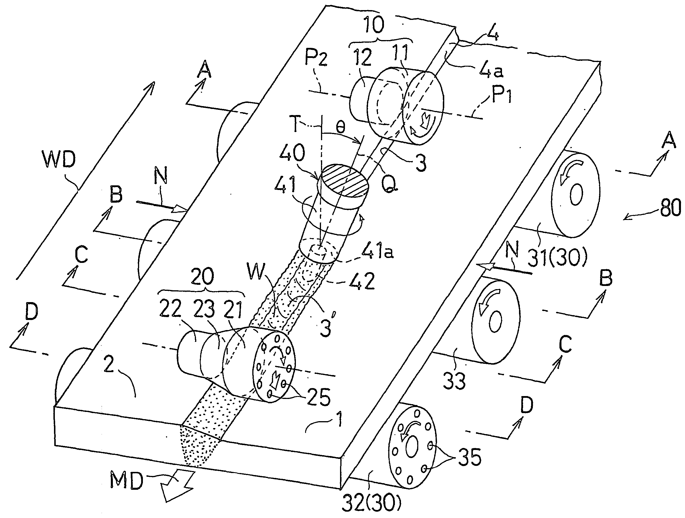
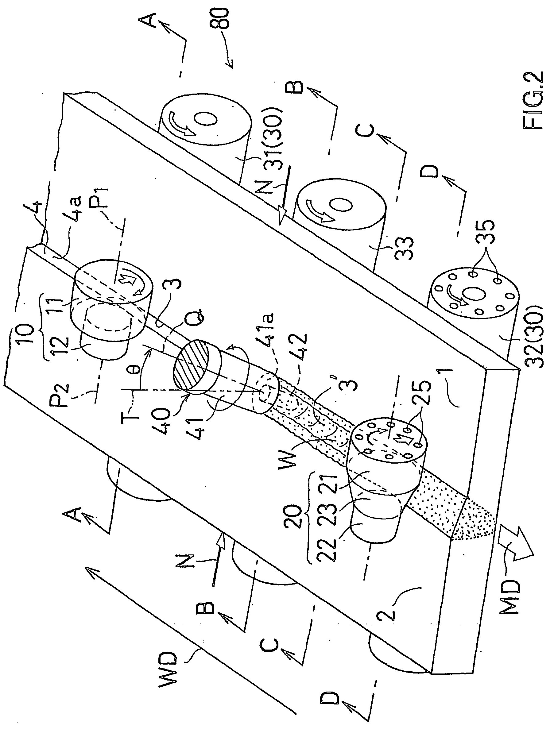
[0177] As a joining tool 40, a tool having a rotor 41 with a probe 41a was prepared. The diameter D of the end face 41a of a rotor 41 was 9 mm, and the protrusion length of the probe 42 from the rotor end face 41a was 2.3 mm. The probe 42 had an M3 screw axial portion.

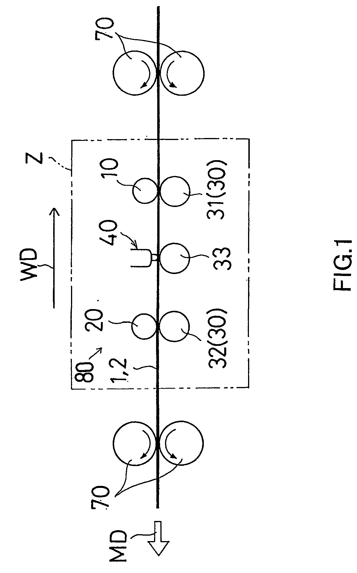
[0178] As forward pressing rollers 10, the rollers as shown in FIGS. 8A and 8B were prepared, while as backward pressing rollers 20, the rollers as shown in FIGS. 8C to 8E were prepared. The structure of each roller was as follows.

[0179] The forward pressing roller 10A shown in FIG. 8A is the sa...

example 1

[0184] The side edge of the first joining member 1 and that of the second joining member 2 were butted against each other with the lower surfaces thereof being flush with each other. Then, the butted portion 3 was joined along the entire length thereof by the joining method of the first embodiment. In this joining, the roller 10B shown in FIG. 8B was used as the forward pressing roller, and the roller 20D shown in FIG. 8D was used as the backward pressing roller. The joining was performed under the following conditions: the rotating speed of the rotor 41 of joining tool 40 was 1,000 rpm; the joining rate was 700 mm / min; the inclination angle .theta. of the rotation axis Q of the joining tool 40 toward the first joining member 1 was 5.degree..

example 2

[0185] The forward pressing roller 10B shown in FIG. 8B and the backward pressing roller 20C shown in FIG. 8C were used. The butted portion 3 of the joining members 1 and 2 was joined along the entire length thereof. Other joining conditions were the same as the aforementioned example 1.


PUM

PropertyMeasurementUnit
insertion depthaaaaaaaaaa
temperatureaaaaaaaaaa
insertion depthaaaaaaaaaa

Abstract

In the friction agitation joining method according to the present invention, two plate-shaped joining members different in thickness, or a first joining member (1) and a second joining member (2), are butted against each other with a level difference formed at upper surface sides thereof. A rotating probe (42) of the joining tool (40) is inserted into the butted portion (3) of said first and second joining members (1,2) from the upper surface sides thereof. Joining-direction front sides of the first joining member (1) and the second joining member (2) with respect to the probe inserted position is pressed by a first front pressing roller (11) and a second front pressing roller (11), respectively, from the upper surface sides thereof. Furthermore, joining-direction lower sides of the first joining member (1) and the second joining member (2) with respect to a probe inserted position from said upper surface sides is pressed by a first lower pressing roller (21) and a second lower pressing roller (22), respectively, from the upper surface sides thereof. In this state, the butted portion (3) is joined by the friction agitation joining method.

Description

[0001] This application claims priority to Japanese Patent Applications Nos. 2001-63267 and 2001-63293 each filed on Mar. 7, 2001, and U.S. Provisional Applications Nos.60 / 303,146 and 60 / 303,158 each filed on Jul. 6, 2001 the disclosure of which is incorporated by reference in its entirety.[0002] This application is an application filed under 35 U.S.C. .sctn.111(a) claiming the benefit pursuant to 35 U.S.C. .sctn.119(e)(1) of the filing data of Provisional Applications Nos.60 / 303,146 and 60 / 303,158 each filed on Jul. 6, 2001 pursuant to 35 U.S.C. .sctn.111(b).[0003] The present invention relates to a friction agitation joining method, a method for manufacturing joined butted members and a friction agitation joining apparatus preferably used for manufacturing metal plate-shaped members used as, for example, flooring materials, wall materials and ceiling materials for transporting device such as automobiles, aircrafts and railroad vehicles.[0004] A friction agitation joining method be...

Claims


Application Information

Patent Timeline
Patent Type & Authority Applications(United States)
IPC IPC(8): B23K20/12
CPCB23K20/122B23K20/126B23K20/1235
Inventor NARITA, MASAYUKIHAMA, YASUYUKIAKIYAMA, HIROSHIHASHIMOTO, TAKENORIJOGAN, SHIGETOSHINAGANO, YOSHITAKA
Owner HONDA MOTOR CO LTD
Why Eureka
Try Eureka