
Gasket flow sensing apparatus and method

a flow sensing and gasket technology, applied in the direction of instruments, heat measurement, volume metering, etc., can solve the problems of difficult and restricted all methods, indirect methods cannot simulate the effect of thermal boundary layers around the sensor, and difficult to u

Inactive Publication Date: 2004-07-29
DANA AUTOMOTIVE SYST GRP LLC
View PDF5 Cites 28 Cited by
  • Summary
  • Abstract
  • Description
  • Claims
  • Application Information

AI Technical Summary

Problems solved by technology

Disadvantages:--Difficult to use
All methods are difficult and are restricted to low frequencies
Indirect methods cannot simulate effect of thermal boundary layers around sensor (which reduces the frequency response).
This complicates the sensor fabrication.
This is due to the fact that noise increases as the square root of the wire resistance.

Method used


Image

  • Gasket flow sensing apparatus and method
  • Gasket flow sensing apparatus and method
  • Gasket flow sensing apparatus and method

Examples


Embodiment Construction

[0144] A test fixture 50 is depicted in FIG. 11 for purposes of simulating the hot wire anemometer system of measuring fluid flow.

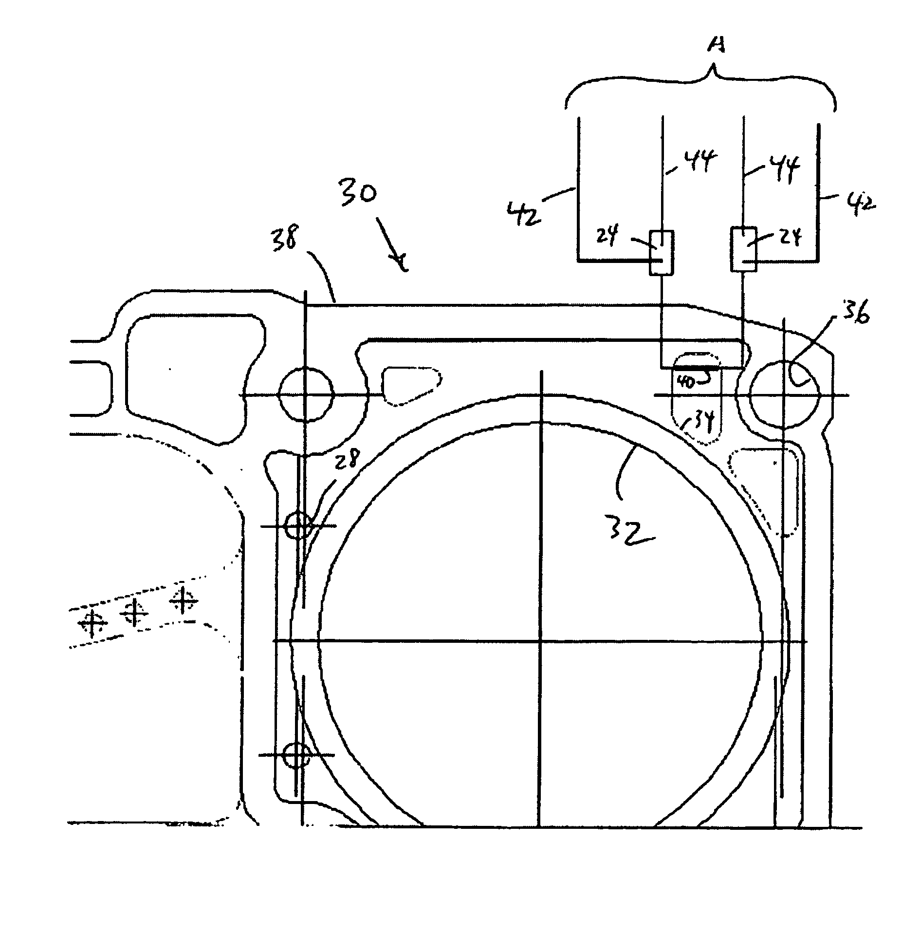
[0145] The test fixture 50 includes a coolant flow aperture 34' across which is deposited a thermal sensing probe 40' as shown. The test fixture has a boundary or extremity 38' similar to the boundary 38 of the gasket 30 described above. In addition, the test fixture 50 incorporates a pair of soldered plates 24', analogous to the plates 24 of the embodiment of the cylinder head gasket 30 of FIG. 2. Also analogously, the current supply wires 42 are directly attached to the soldered plates 24 as described in the previous embodiment, and share the plates with the voltage measuring wires 44'.

[0146] To the extent that the test fixture 50 is not exposed to the harsh heat and temperature environment of an internal combustion engine, i.e., the test fixture environment was subject only to a temperature of up to 150.degree. centigrade to simulate a hot oil environm...


PUM


Abstract

An improved fluid flow sensor for measuring changes in temperatures of fluids flowing through apertures of a multiple-layered gasket is embedded between layers of the gasket. A thermal resistor type of sensor based upon hotwire anemometer technology in a preferred embodiment is responsive to changes in fluid temperature and flow velocity. A primary resistance with external current leads and separate auxiliary leads for voltage sensing are employed, wherein changes in resistance are virtually linearly proportional to changes in temperature. A four-point probe measurement method provides a most accurate reading of the temperature data to the extent that resistance associated with lead and contact resistances are minimized. The thermal resistor sensor is constructed of relatively thin layers of dielectric and electrically conducting materials having a low thermal mass, wherein the dielectric layers serve as support and electrical insulation to protect the sensor from environmental deterioration.

Description

[0001] This application claims priority from U.S. Provisional Patent Application No. 60 / 297,701, filed on Jun. 12, 2001, the contents of which are incorporated herein by reference in their entirety.[0002] 1. Field of Invention[0003] The present invention relates generally to flow rate sensing apparatus, and particularly to micro-fluidic methods applied to cylinder head gaskets for internal combustion engines. More specifically, the invention relates to apparatus and methods for measuring temperatures of fluids passing through apertures of cylinder head gaskets.[0004] 2. Description of the Prior Art[0005] It is known to employ electronic sensors in cylinder head gaskets for sealing between engine components including, for example, the block and cylinder head of a multi-cylinder internal combustion engine. In one case, the gasket comprises a sealing plate having several combustion chamber orifices, and combustion chamber sealing elements at the edges of the sealing plate surrounding t...

Claims


Application Information

Patent Timeline
IPC IPC(8): G01F1/692G01F1/696G01K7/16
CPCG01F1/692G01K7/16G01F1/6965
Inventor POPIELAS, FRANK W.ROBINS, HOWARD M.FOSTER, JEFFERY A.
Owner DANA AUTOMOTIVE SYST GRP LLC
Learn More