Discharge lamp for dielectrically impeded discharges having a corrugated cover plate structure

a dielectrically impeded discharge and discharge lamp technology, which is applied in the direction of discharge tube luminescnet screens, transit-tube circuit elements, cathode-ray/electron beam tube circuit elements, etc., can solve the problem that the top plate is not necessarily transparent in its entire extent, the curvature of the line of section is not produced, and the small roughness that can certainly indicate the edges and tips on a very small length scale is not importan

Inactive Publication Date: 2004-08-12
PATENT TREUHAND GESELLSCHAFT FUR ELECTRIC GLUEHLAMPEN MBH
View PDF7 Cites 4 Cited by
  • Summary
  • Abstract
  • Description
  • Claims
  • Application Information

AI Technical Summary

Problems solved by technology

In addition, the top plate is not necessarily transparent in its entire extent.
In other words, excessively small radii of curvature of the line of section are not to be produced over the averaging length s.
Small instances of roughness that can certainly indicate edges and tips on a very small length scale are, however, unimportant in this case, because the modulations of intensity caused by them are imperceptible, or slightly perceptible, owing to additional diffusing elements or else to the limited resolution of the human eye.
In particular, it is scarcely possible with such structures to ensure a substantially constant material thickness.
For the rest, such additions usually have the disadvantage that they release gases upon heating during lamp production so that extensive pumping operations are required to keep the discharge medium pure.
Furthermore, the processing times during production are shortened, because thinner plate materials and therefore smaller thermal capacitances occur.

Method used


Image

  • Discharge lamp for dielectrically impeded discharges having a corrugated cover plate structure
  • Discharge lamp for dielectrically impeded discharges having a corrugated cover plate structure
  • Discharge lamp for dielectrically impeded discharges having a corrugated cover plate structure

Examples


Embodiment Construction

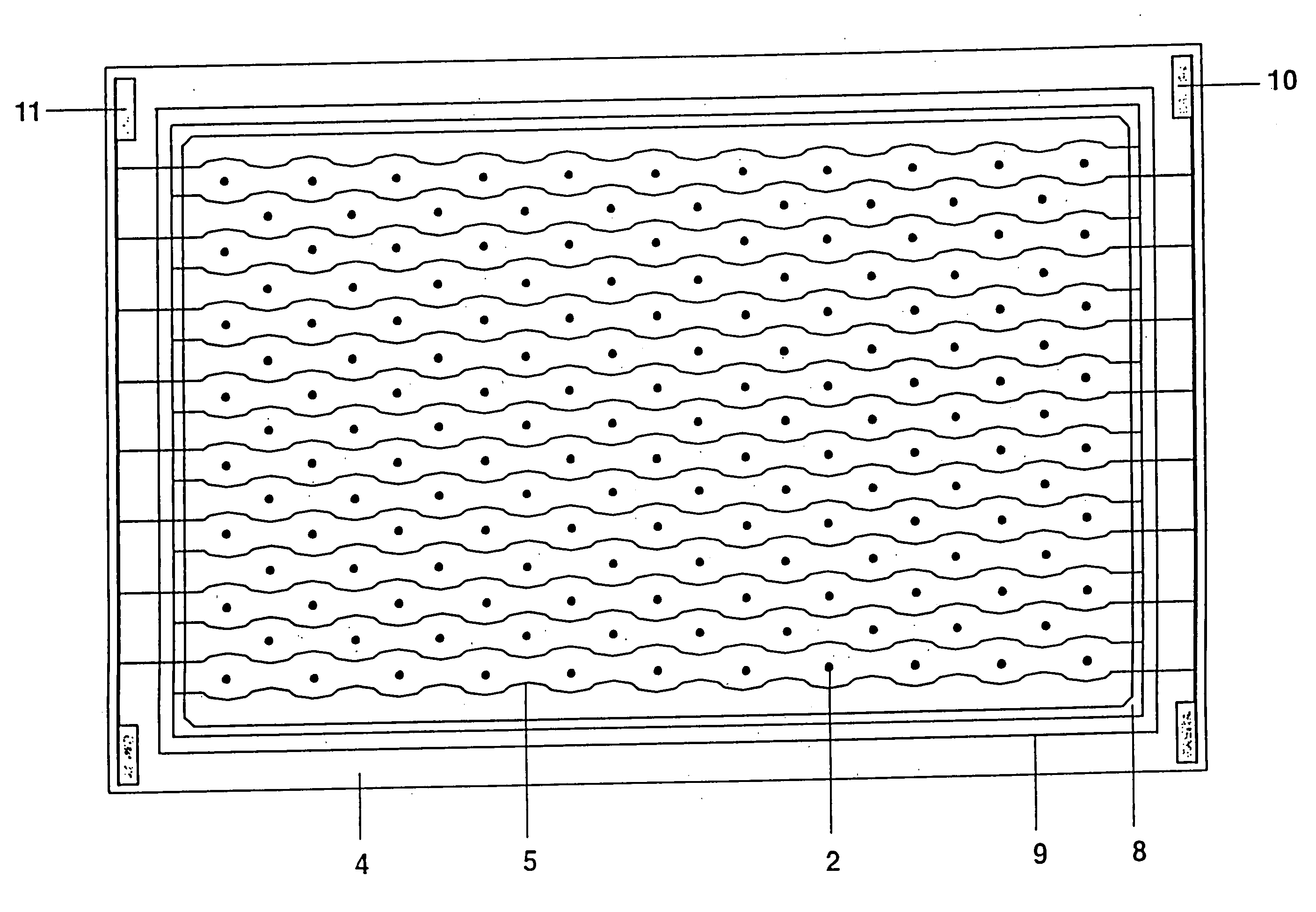
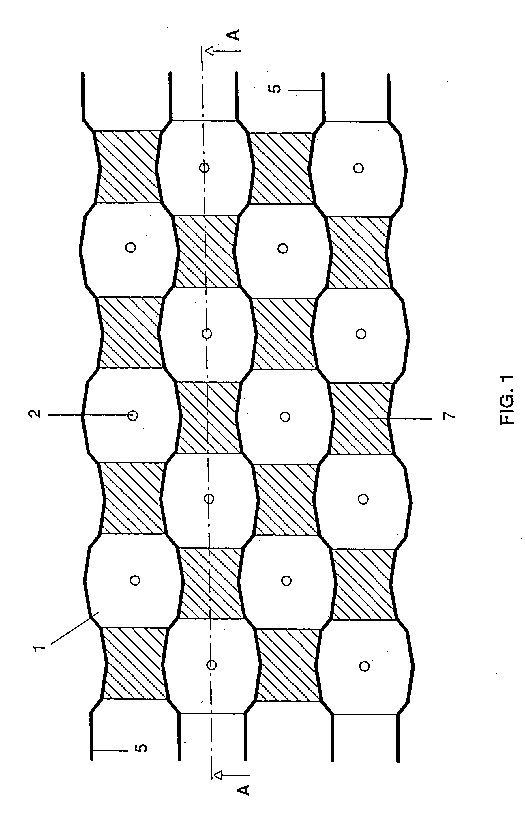
[0045] FIG. 1 shows a schematic plan view of an arrangement of supporting projections and individual discharge regions that is like a chessboard. In this case, the small circles denoted by 2 correspond to the round extremes, which point downward, that is to say toward the base plate 4, of sinusoidal supporting projections of the top plate 3 situated above in the cross-sectional view (A-A) in FIG. 2a.

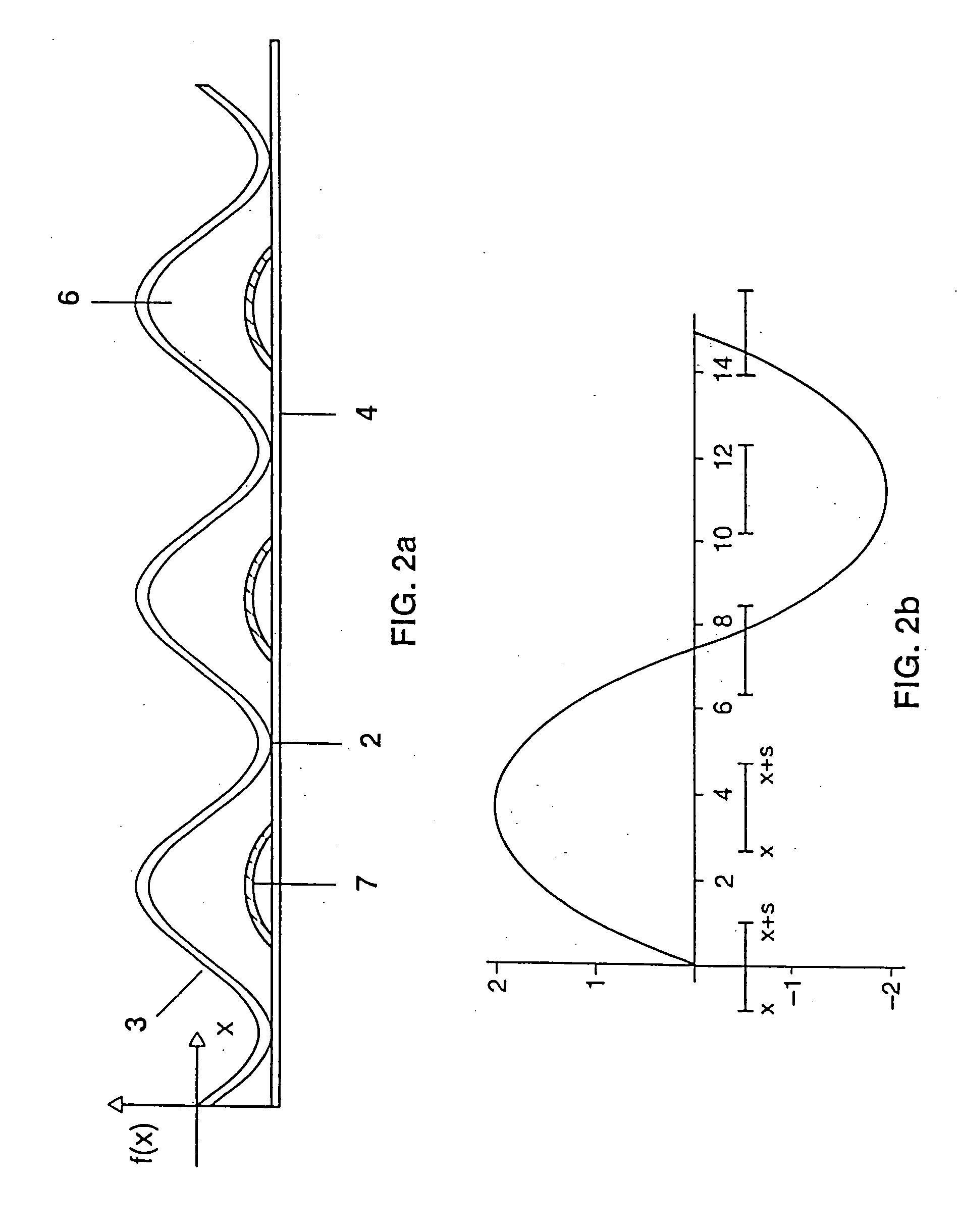
[0046] FIG. 2a shows that along the line A-A in FIG. 1 the top plate 3 has a sinusoidal profile that also occurs identically in other parallel sections through the respective extremes 2 and in orthogonal sections through the extremes 2. The lower "round tips" 2 of the sinusoidal shape bear in a touching fashion against the base plate 4, while the upper "round tips", that is to say the maxima on the sinusoidal shape, respectively rise above the highest regions of the discharge space 6.

[0047] The sinusoidal shape illustrated in FIG. 2a and FIG. 2b can be described with reference to the coo...


PUM


Abstract

The invention relates to a discharge lamp having a base plate and a cover which is arranged in an essentially parallel manner thereto and which is corrugated in order to enable light to exit in a homogeneous manner.

Description

[0001] The present invention relates to discharge lamps that are designed for dielectrically impeded discharges and are also designated as silent discharge lamps or dielectric barrier discharge lamps. Such discharge lamps have an electrode set for producing discharges in a discharge medium that is located in a discharge space of the lamp. Provided in this case between at least one part of the electrode set and the discharge medium is a dielectric layer that forms the dielectric impediment. In the case of lamps in which it is fixed whether the electrodes operate as cathodes or anodes, at least the anodes are dielectrically separated from the discharge medium.PRIOR ART[0002] Such lamps are prior art and have recently been enjoying increasing attention, chiefly because it is possible with the aid of a pulsed mode of operation (U.S. Pat. No. 5,604,410) to achieve relatively high efficiencies that make use as a source of visible light or as a UV radiator seem attractive for various field...

Claims


Application Information

Patent Timeline
Patent Type & Authority Applications(United States)
IPC IPC(8): H01J65/00H01J61/30H01J61/33H01J65/04
CPCH01J61/305H01J65/046H01J61/33H01J65/04
Inventor HITZSCHKE, LOTHARVOLLKOMMER, FRANK
Owner PATENT TREUHAND GESELLSCHAFT FUR ELECTRIC GLUEHLAMPEN MBH
Why Eureka
Try Eureka