Discharge lamp having at least one external electrode, adhesive layer, and carrier film

a technology of external electrodes and discharge lamps, applied in the manufacture of electrode systems, cold cathode manufacturing, electric discharge tubes/lamps, etc., can solve the problems of inability to discharge and impair the homogeneity of the luminous density of the lamp to an unacceptable extent, and achieve the effect of improving the reliability of the discharge lamp and simplifying the manufacturing process

Inactive Publication Date: 2007-11-20
PATENT TREUHAND GESELLSCHAFT FUR ELECTRIC GLUEHLAMPEN MBH
View PDF15 Cites 0 Cited by
  • Summary
  • Abstract
  • Description
  • Claims
  • Application Information

AI Technical Summary

Benefits of technology

[0004]It is an object of the present invention to provide a discharge lamp having at least one external electrode which is simpler to fabricate. A further aspect is the improved reliability of the discharge lamp.
[0007]The advantage of the solution according to the invention is that the laminate can be prefabricated and can then be adhesively bonded in complete form to an outer side of the discharge vessel. The process is therefore also very suitable for automated mass production. In addition, the production of the lamp is more economical as a result. This solution is particularly advantageous in the case of discharge lamps having a plurality of strip-like electrodes, such as the flat lamp disclosed in U.S. Pat. No. 5,994,849 mentioned at the beginning, since then all the electrodes, together with the laminate, can be adhesively bonded to the discharge vessel in a single operation. Here, the adhesive can be applied separately to an area of the discharge vessel provided for the purpose immediately before the adhesive bonding of the laminate, or to the laminate itself. However, in order to simplify lamp fabrication it may also be advantageous for the laminate to already be provided with an adhesive layer. For improved stock keeping and handling during fabrication, the adhesive layer is preferably protected by a cover film, which is removed only immediately before the adhesive bonding of the laminate. In order that the adhesive layer does not inadvertently separate from the laminate when the cover film is pulled off, the adhesive layer preferably has a stabilizing agent, for example fibers embedded in the adhesive layer. Alternatively suitable as an adhesive layer is also a thin film serving as a stabilizing agent, which is coated on both sides with adhesive. In selecting the type and thickness of the adhesive, it is necessary to take into account that the adhesive layer fills all the cavities between the electrode tracks, in order that if possible no air inclusions arise during adhesive bonding. This is because, if relatively large air inclusions form, at this point some of the electrode tracks lift off the outer side of the discharge vessel, as a result of which, in the least beneficial case, the discharge fails at this point. This can in turn impair the homogeneity of the luminous density of the lamp to an unacceptable extent and is therefore undesired. For example, an adhesive such as is used in the tesa 4980 adhesive tape from Tesa AG has proven to be suitable. Good results were achieved with adhesive layers whose respective thickness lies in the range between about 40 to 200 μm, preferably between about 60 to 100 μm. In this case, it has surprisingly been shown that no undesirably large voltage drops occur across the electrodes.
[0008]The laminate is preferably oriented in such a way that the at least one electrode similar to a conductor track is arranged between the relevant outer side of the discharge vessel and the carrier film. This has the advantage that the carrier film, in addition to acting as a carrier, simultaneously acts as a protective film against external effects and as a protection against contact.
[0012]A first embodiment relates to what are known as aperture lamps having external electrodes, which have a tubular discharge vessel. This lamp type has at least one, typically two, strip-like external electrodes, which are oriented parallel to the longitudinal axis of the tubular discharge vessel. According to the invention, at least one electrode track laminated to a carrier film is adhesively bonded on parallel to the longitudinal axis of the tubular discharge vessel. In the case of two parallel electrode tracks, these are laminated into the carrier film with a predefined mutual spacing. This means that, after the laminate has been adhesively bonded on to the outside of the tubular discharge vessel, the two electrode tracks are arranged at the desired position. In addition, the laminate is adhesively bonded on in such a way that the aperture of the lamp, through which the light is emitted, remains free. As compared with the conventional solution, in which a translucent heat-shrink tube of plastic is subsequently applied to the electrodes typically adhesively bonded on, this has the advantage that here there is no reduction of the luminous flux passing through the aperture as a result of a heat-shrink tube.

Problems solved by technology

This is because, if relatively large air inclusions form, at this point some of the electrode tracks lift off the outer side of the discharge vessel, as a result of which, in the least beneficial case, the discharge fails at this point.
This can in turn impair the homogeneity of the luminous density of the lamp to an unacceptable extent and is therefore undesired.

Method used


Image

  • Discharge lamp having at least one external electrode, adhesive layer, and carrier film
  • Discharge lamp having at least one external electrode, adhesive layer, and carrier film
  • Discharge lamp having at least one external electrode, adhesive layer, and carrier film

Examples


Embodiment Construction

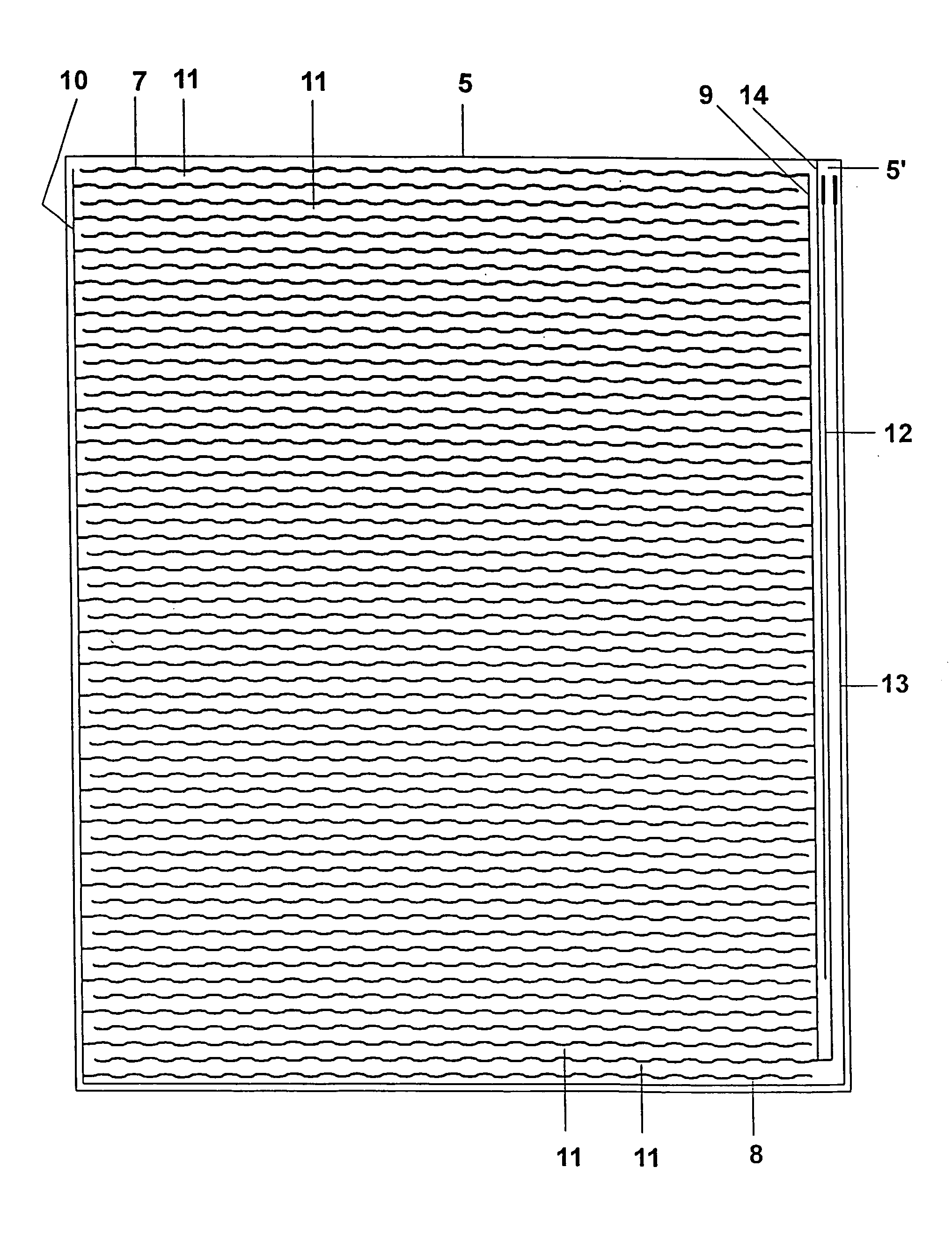
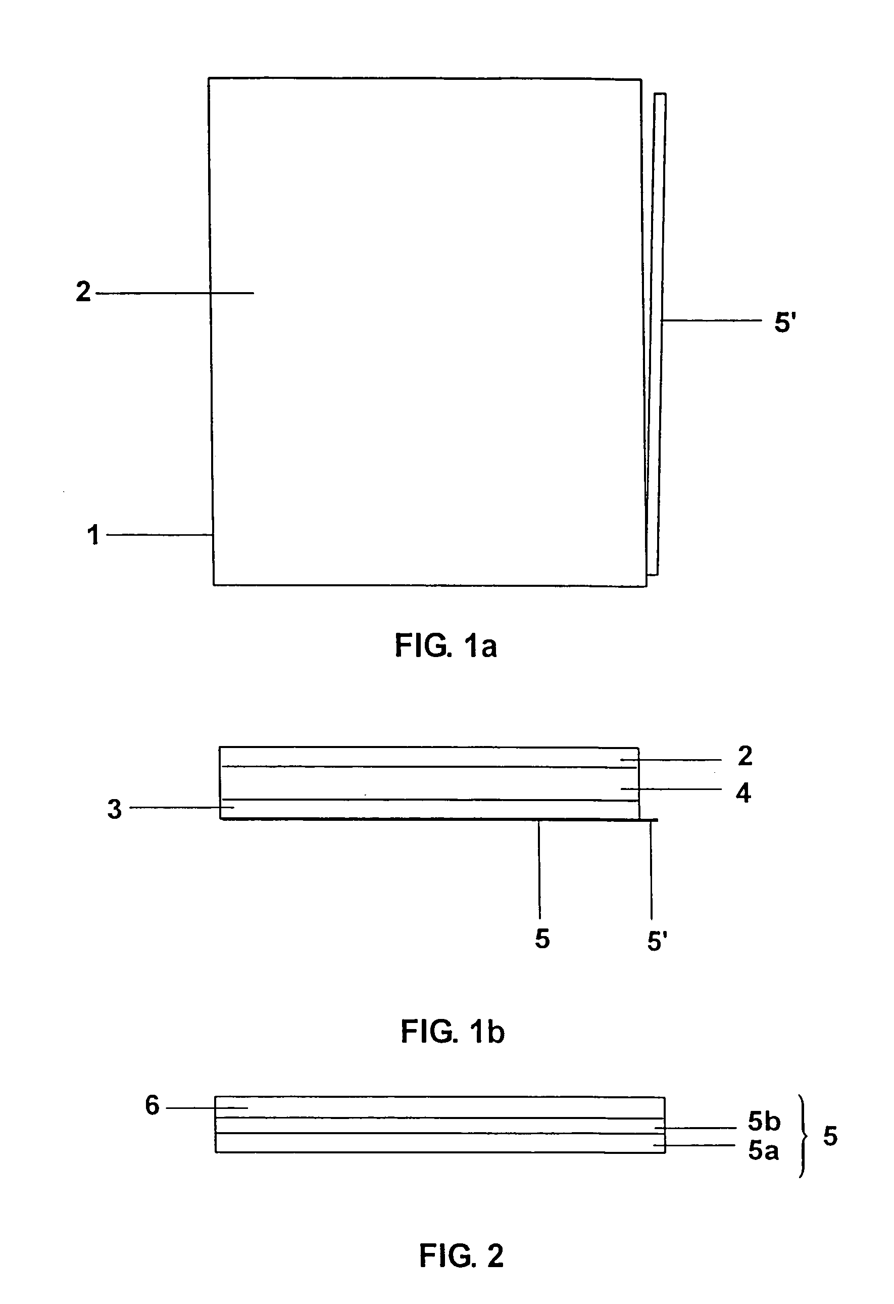
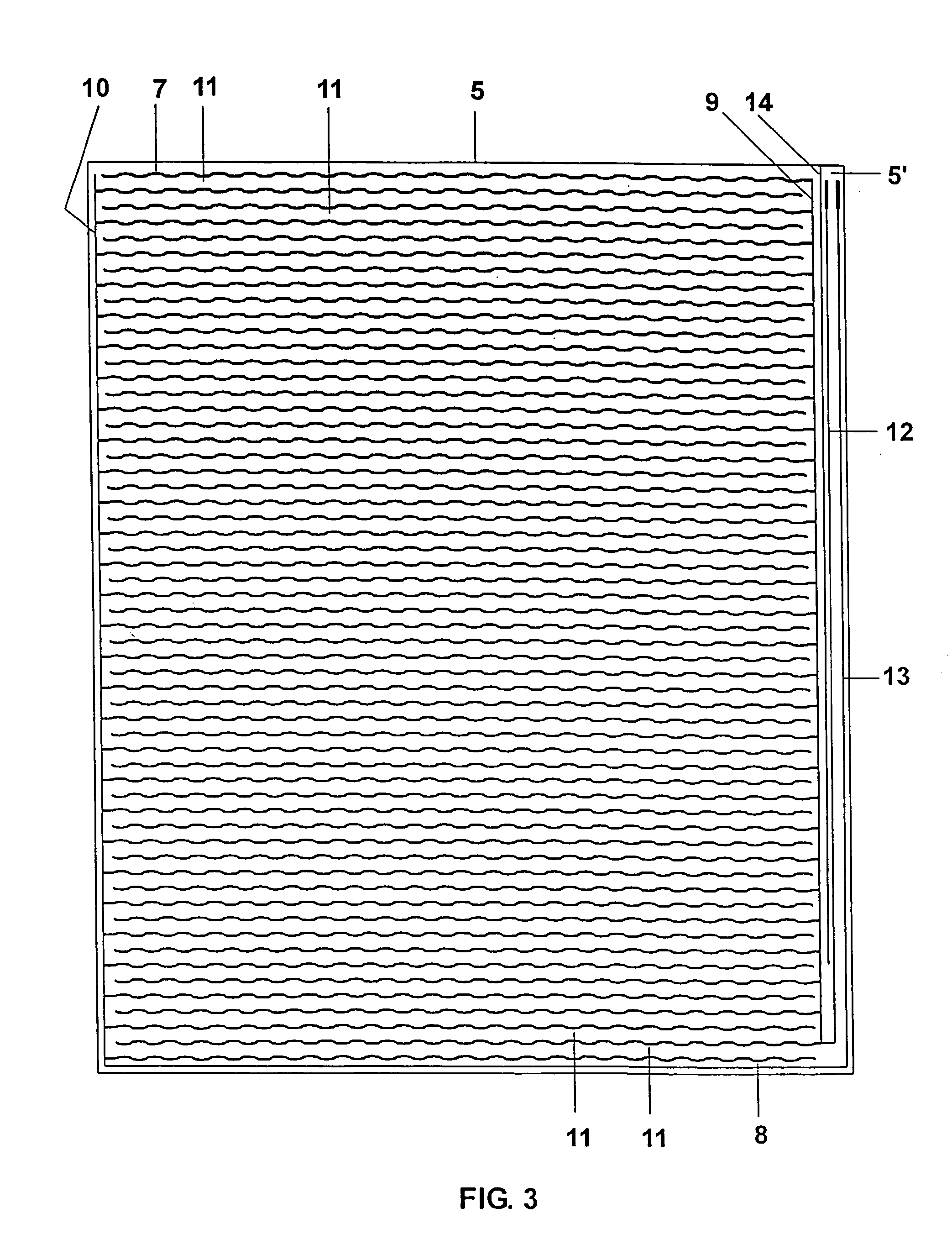
[0020]FIGS. 1a, 1b show in schematic form a flat lamp 1 having a diagonal of 21.3″ and a side ratio of 4:3 in plan view and side view, respectively. The discharge vessel of the flat lamp 1 is formed by a front plate 2, a baseplate 3 and a frame 4 arranged between them, the frame 4 connecting the two plates 2, 3 to each other in a gas tight manner. Alternatively, it is also possible to dispense with a frame if baseplate and front plate are not both completely flat but, at least in the edge region, are shaped in such a way that the frame is, as it were, incorporated in at least one of the two plates. For further details in this regard, reference is made to the documents U.S. Pat. No. 5,994,849 and WO 03 / 017312 already cited, whose disclosure content in this regard is hereby incorporated by reference. In the interior of the discharge vessel there is xenon and neon with a partial filling pressure of about 10 kPa and about 20 kPa, respectively. Adhesively bonded to the outer side of the ...


PUM


Abstract

In a discharge lamp having a discharge vessel and external electrodes, at least one electrode similar to a conductor track is an integral part of a laminate (5) which is adhesively bonded to the outer side of the discharge vessel and includes a carrier film made of electric insulating material.

Description

TECHNICAL FIELD[0001]The invention is based on a discharge lamp in which at least one electrode, also called the external electrode for short in the following text, is arranged on the outer side of the discharge vessel.[0002]Discharge lamps of this type fall under the general designation “dielectric barrier discharge lamps (DBD lamps)”, here the wall of the discharge vessel acting as a dielectric barrier for the respective electrode arranged on the outer side of the discharge vessel. The form of the discharge vessel plays a subordinate role in this connection, however. Known amongst others are tubular lamp types which, for example in office automation (OA), are used for photocopiers, fax machines and scanners, and also flat lamp types, which are used inter alia in general lighting, for film lamps and as backlighting for liquid-crystal displays (LCD).BACKGROUND ART[0003]U.S. Pat. No. 5,994,849 discloses a flat lamp having external electrodes. The discharge vessel comprises a flat bas...

Claims


Application Information

Patent Timeline
Patent Type & Authority Patents(United States)
IPC IPC(8): H01J11/00H01J9/02H01J9/20H01J17/16H01J61/04H01J61/30H01J61/54H01J65/00H01J65/04
CPCH01J65/00H01J61/305H01J65/04
Inventor HITZSCHKE, LOTHARVOLLKOMMER, FRANK
Owner PATENT TREUHAND GESELLSCHAFT FUR ELECTRIC GLUEHLAMPEN MBH
Why Eureka
Try Eureka