Ball/roller bearing cleaning method and apparatus thereof

a technology of ball/roller bearing and cleaning method, which is applied in the direction of cleaning hollow objects, cleaning using liquids, mechanical equipment, etc., can solve the problems of difficult to completely remove dirt particles between the rolling body and the retainer insufficient cleaning effect, and parts of the bearing to be cleaned, so as to improve the cleaning effect

Inactive Publication Date: 2004-09-02
NSK LTD
View PDF2 Cites 3 Cited by
  • Summary
  • Abstract
  • Description
  • Claims
  • Application Information

AI Technical Summary

Benefits of technology

[0010] According to the present ball / roller bearing cleaning method, into spaces which exist between the raceway surface of the inner ring and the raceway surface of the outer ring of the bearing to be cleaned and also surround the rolling bodies and retainer, the cleaning liquid is supplied from the axial direction of the bearing to be cleaned, whereby dirt particles caught in the part where the cleaning liquid cannot be applied directly, that is, dirt particles existing between the surfaces of the rolling bodies and retainer can be removed positively.
[0030] According to this structure, in a case where the cleaning liquid cannot be forcibly supplied into the interior portion of the bearing to be cleaned, by rotating the freely rotatable inner ring or outer ring of the bearing to be cleaned using a motor or an air turbine, the bearing to be cleaned can be cleaned while rotating the same, which can enhance the cleaning effect.

Problems solved by technology

However, in the above-mentioned conventional ultrasonic cleaning method, due to the characteristic of ultrasonic wave, ultrasonic wave is not able to effect the interior part of the bearing to be cleaned, which result in insufficient cleaning effect.
Especially, since the bearing to be cleaned is simply immersed in the cleaning liquid, it is difficult to completely remove dirt particles existing between the rolling bodies and retainer of the bearing to be cleaned.
Also, in the latter ultrasonic cleaning method, although the area of the bearing where the jetted cleaning liquid is applied can be cleaned, the cleaning liquid is splashed back from the cleaning liquid applied bearing portions, so that the portions of the bearing, where the jetted cleaning liquid cannot be applied directly, cannot be cleaned to a satisfactory degree.
Therefore, it is difficult to completely remove dirt particles between the parts of the bearing to be cleaned, for example, between the rolling bodies and retainer of the bearing to be cleaned.
Also, referring to an ultrasonic cleaning apparatus employed in enforcing the ultrasonic cleaning method, the structure thereof is complicated: that is, the ultrasonic cleaning apparatus is capable of cleaning a ball / roller bearing of a relatively large size but is not suitable to clean a ball / roller bearing of a small size.
This two-stage cleaning method is effective in the following case: that is, a large number of hard foreign substances are present in the interior portion of the bearing to be cleaned and thus, in case where the bearing to be cleaned is rotated in this state, there is a fear that the raceway surfaces of the inner ring and outer ring as well as the surfaces of the rolling bodies of the bearing to be cleaned can be damaged.

Method used


Image

  • Ball/roller bearing cleaning method and apparatus thereof
  • Ball/roller bearing cleaning method and apparatus thereof
  • Ball/roller bearing cleaning method and apparatus thereof

Examples


first embodiment

[0046] (First Embodiment)

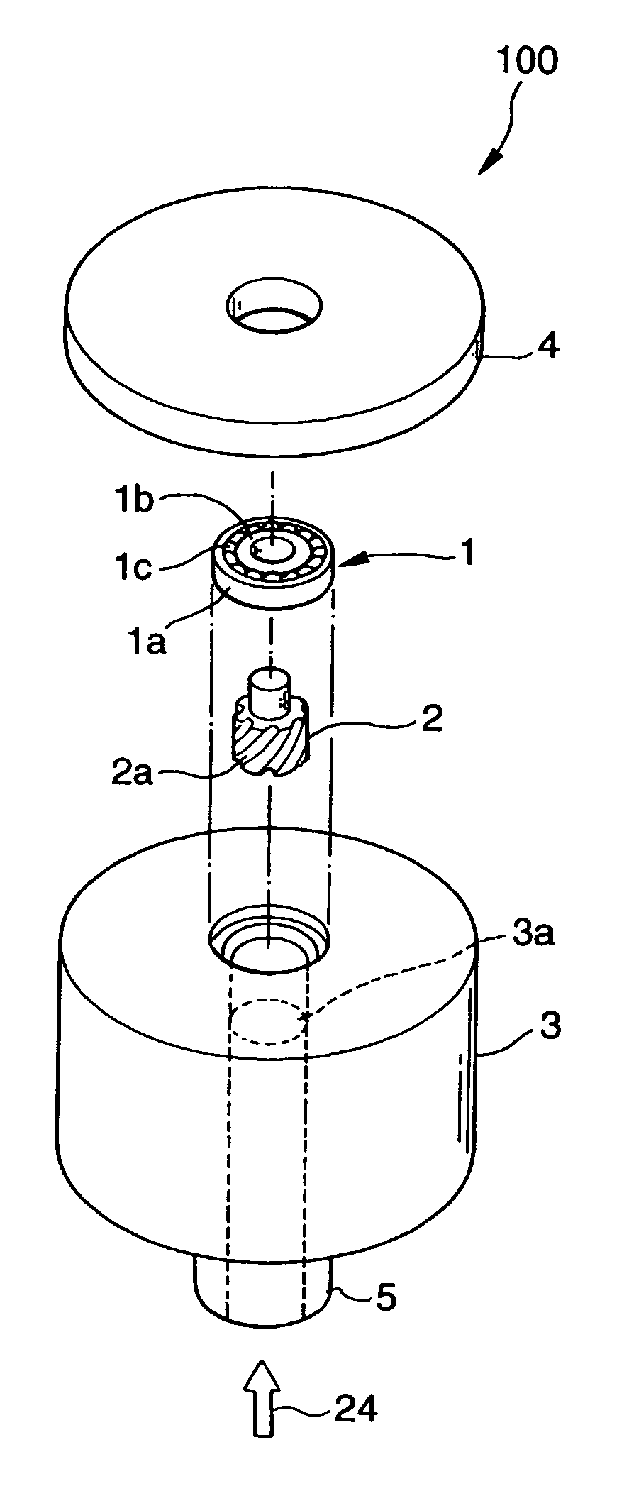
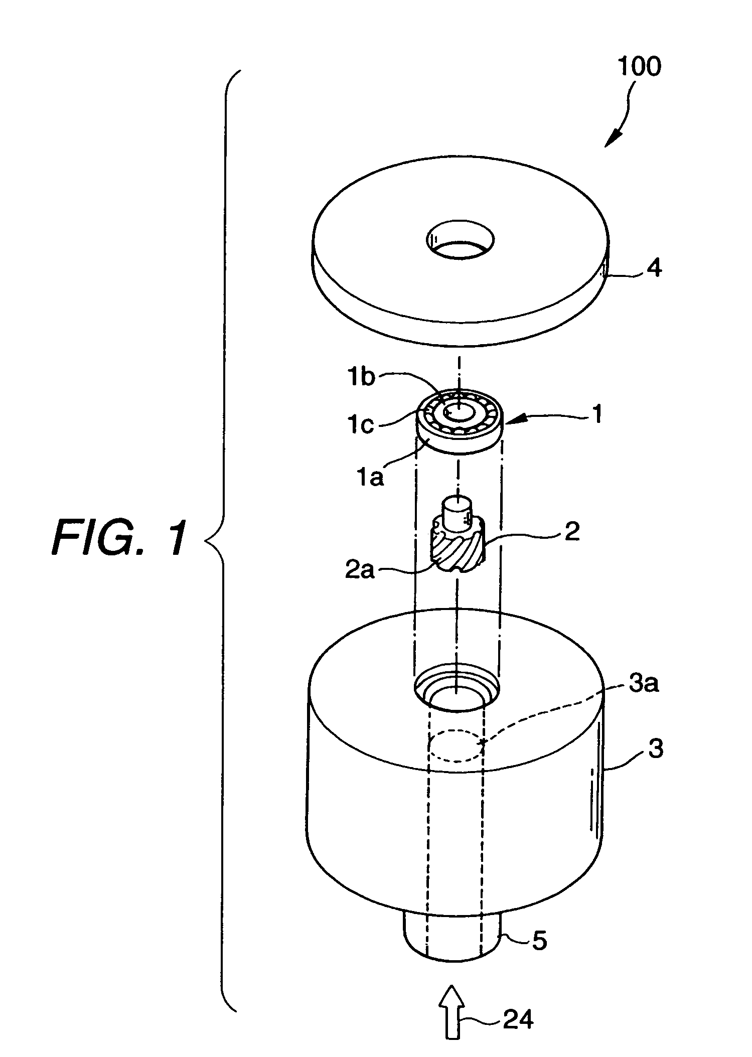
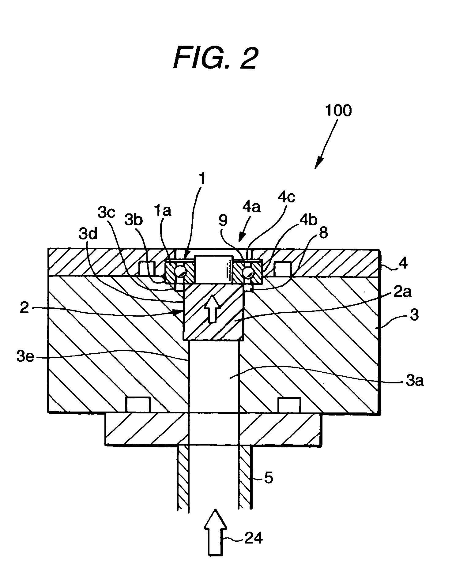
[0047] FIG. 1 is a schematic exploded view of a cleaning apparatus for cleaning a ball / roller bearing according to a first embodiment of the invention, and FIG. 2 is a sectional front view of the ball / roller bearing cleaning apparatus shown in FIG. 1, showing the structure thereof.

[0048] As shown in FIGS. 1 and 2, the ball / roller bearing cleaning apparatus 100 according to the first embodiment comprises a cylindrical-shaped rotary die 2, the cylindrical portion of which is to be fitted with an inner ring 1b of a ball / roller bearing to be cleaned (which is hereinafter referred to as a bearing to be cleaned) 1, a holder 3 for storing the bearing to be cleaned 1 and cylindrical-shaped rotary die 2 in its communicating hole 3a serving as a cleaning liquid flow passage, a cover 4 for covering the upper surface of the holder 3, and a pipe 5 which is connected to the communicating hole 3a of the holder 3 and is used to supply cleaning liquid.

[0049] In the communica...

second embodiment

[0063] (Second Embodiment)

[0064] Now, FIG. 3 is a sectional front view of a ball / roller bearing cleaning apparatus according to a second embodiment of the invention, showing the structure thereof. By the way, in FIG. 3, parts used here in common with the previously described FIGS. 1 and 2 are given the same designations and thus the description thereof is omitted here.

[0065] As shown in FIG. 3, in a ball / roller bearing cleaning apparatus 200 according to the second embodiment, there is used a conical-shaped rotary die 10 including a lower end face with the area thereof reduced, in order to be able to reduce a force which acts on a bearing to be cleaned in the axial direction thereof.

[0066] According to this structure, because the diameter of the hole 3a of the holder 3 is reduced, there can be reduced the magnitude of a force applied onto the inner ring 1b of the bearing to be cleaned 1 in the axial direction thereof through the conical-shaped rotary die 10, which can prevent a poss...

third embodiment

[0068] (Third Embodiment)

[0069] Now, FIG. 4 is a sectional front view of a ball / roller bearing cleaning apparatus according to a third embodiment of the invention, showing the structure thereof. In FIG. 4, parts used here in common with the previously described FIGS. 1, 2 and 3 are given the same designations and thus the description thereof is omitted here.

[0070] By the way, in the bearing to be cleaned 1, hard dirt particles could exist in the interior portion of the bearing to be cleaned 1. In such case, if the bearing to be cleaned 1 is rotated for cleaning the same, the hard dirt particles could damage the bearing itself (in particular, the raceway surfaces of the raceways thereof and the rolling surfaces of the rolling bodies thereof).

[0071] Now, the ball / roller bearing cleaning apparatus 300 according to the present embodiment is especially effective when hard dirt particles exist in the interior portion of the bearing to be cleaned 1.

[0072] That is, as shown in FIG. 4, the b...


PUM


Abstract

The present ball / roller bearing cleaning method is a method which, using cleaning liquid 24, cleans a bearing to be cleaned 1 composed of an inner ring 1b, an outer ring 1a, a rolling bodies 1c and a retainer. In the cleaning method, the cleaning liquid 24 is made to flow through the bearing to be cleaned 1 from the axial direction of the present bearing 1 into spaces in which the raceway surfaces of the inner and outer rings 1b and 1a of the bearing to be cleaned 1 surround the rolling bodies 1c and retainer. For example, a cylindrical-shaped rotary die 2 having spiral grooves 2a is interposed into a cleaning liquid supply passage, and the cleaning liquid 4 is supplied to thereby rotate the cylindrical-shaped rotary die 2, whereby the cleaning liquid having high pressure can be supplied to the bearing to be cleaned 1 from the cylindrical-shaped rotary die 2.

Description

[0001] 1. Field of the Invention[0002] The present invention relates to a method which, in a process of manufacturing where high cleanliness is required to a ball / roller bearing, cleans an assembled ball / roller bearing before supplying oil or grease.[0003] 2. Description of the Related Art[0004] Conventionally, as a method for cleaning a mechanical part, an ultrasonic cleaning method has been mainly used. In this ultrasonic cleaning method, for example, as shown in FIG. 14, a bearing 1 to be cleaned stored in a washing basket 50 is cleaned within a cleaning vessel 22 which includes an ultrasonic vibration plate 20 mounted on the bottom portion thereof and is filled with cleaning liquid 24.[0005] Also, as a method for cleaning a ball / roller bearing, a patent is disclosed, for example, in Japanese Patent Unexamined Publication No. Hei.11-138111 (JP-A-11-138111). In this cleaning method, a bearing to be cleaned is disposed on a rotary table where cleaning liquid is jetted onto the bear...

Claims


Application Information

Patent Timeline
Patent Type & Authority Applications(United States)
IPC IPC(8): B08B3/02B08B3/12B08B9/00F16C33/64
CPCB08B3/02B08B2203/0288B08B9/00B08B3/12F16C2235/00
Inventor MIZUNO, HIROKITOKURA, SHIGEOTONOOKA, KATSUHISASHIBAZAKI, HIROSHI
Owner NSK LTD
Why Eureka
Try Eureka