Backlight unit

a backlight unit and backlight technology, applied in the direction of instruments, lighting and heating apparatus, planar/plate-like light guides, etc., can solve the problems of disadvantage of ccfl and difficulty in viewing images on such a display device in dark places

Active Publication Date: 2004-09-02
SAMSUNG DISPLAY CO LTD
View PDF4 Cites 106 Cited by
  • Summary
  • Abstract
  • Description
  • Claims
  • Application Information

AI Technical Summary

Problems solved by technology

Thus, it is difficult to view an image on such a display device in dark places.
However, the CCFL is disadvantageous since it is operated by a high frequency AC signal and has a narrow operational temperature range.
Such a problem occurs in an LGP having a scattering pattern as well as an LGP having a hologram pattern.

Method used


Image

  • Backlight unit
  • Backlight unit
  • Backlight unit

Examples


Embodiment Construction

[0048] Exemplary embodiments of the present invention will now be described with reference to the accompanying drawings. The described exemplary embodiments are intended to assist the understanding of the invention, and are not intended to limit the scope of the invention in any way.

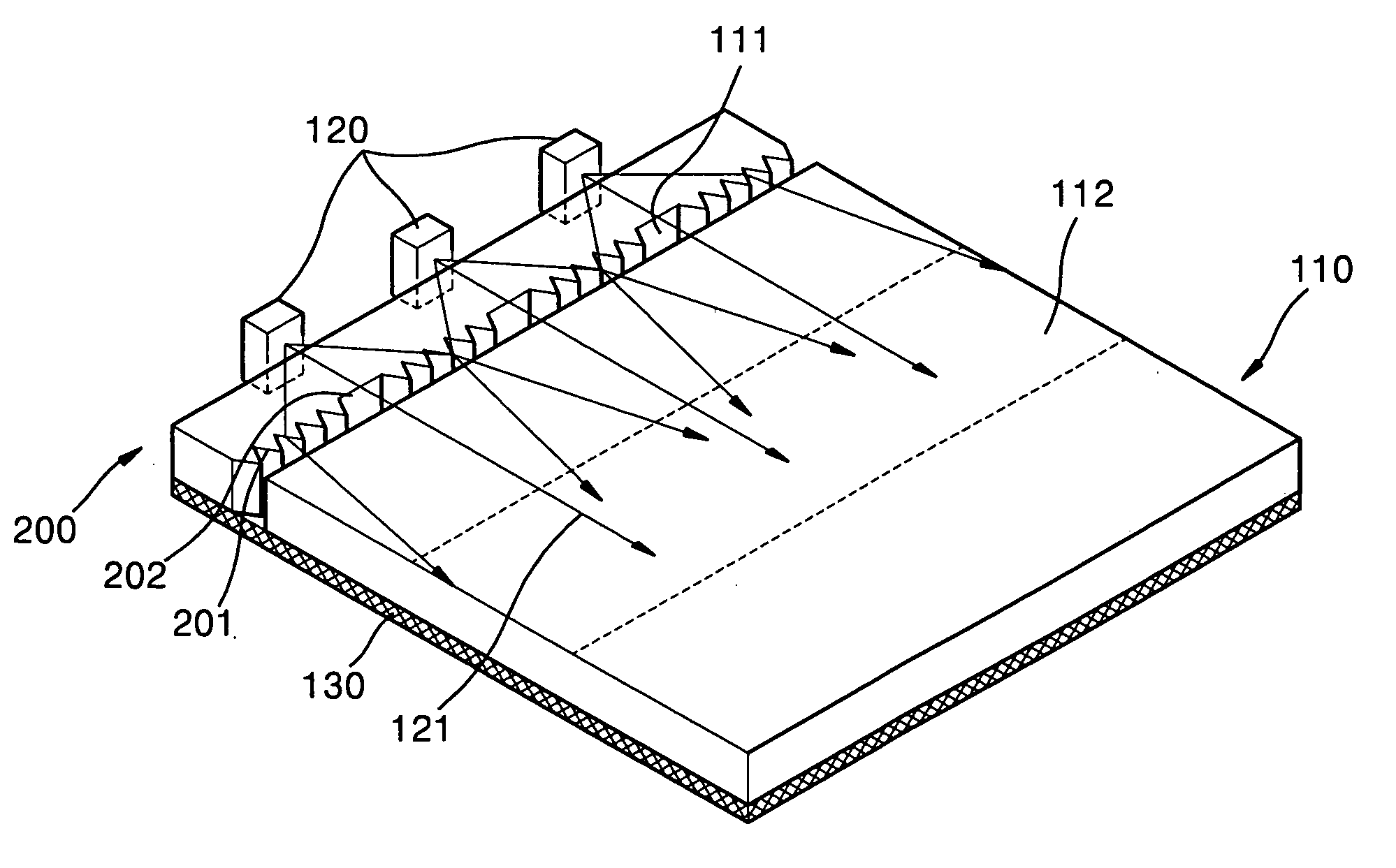
[0049] FIG. 6 is a schematic perspective view of a backlight unit according to a first embodiment of the present invention, and FIG. 7 is a plan view of the backlight unit of FIG. 6.

[0050] Referring to FIGS. 6 and 7, three light emitting diodes (LEDs) 120, which are point light sources, are installed along an edge 111 of a light guide panel (LGP) 110, and a prism array 200 is installed between the LGP 110 and the LEDs 120. Also, a transparent portion 202, in which a prism pattern 201 is not formed, is installed in an area through which optical axes 121 of the LEDs 120 passes. A hologram pattern 130 is formed at a rear surface of the LGP 110.

[0051] The LGP 110 is made of a transmissive material, such as a...


PUM

PropertyMeasurementUnit
angleaaaaaaaaaa
angleaaaaaaaaaa
angleaaaaaaaaaa

Abstract

A backlight unit is provided including a light guide panel (LGP), a point light source emitting light at an edge of the LGP; and a refraction member being positioned between the point light source and the LGP and refracting the light emitted from the point light source toward the optical axis of the point light source in order to reduce the azimuth angle of the light that is incident upon the LGP. The refraction member includes a prism array in which a V-shaped prism pattern is repeatedly arrayed, the apex of the prism pattern facing the edge of the LGP, and a transparent portion that prevents the light from being totally reflected by the prism pattern in a region along an optical axis of the light source.

Description

[0001] This application claims the benefit of Korean Patent Application No. 2002-67969, filed Nov. 4, 2002 in the Korean Intellectual Property Office, the disclosure of which is incorporated herein in its entirety by reference.[0002] 1. Field of the Invention[0003] The present invention relates to a backlight unit, and more particularly, to an edge light backlight unit using a light guide panel (LGP) and a point light source.[0004] 2. Description of the Related Art[0005] In general, flat panel displays are largely classified into light emitting displays and light receiving displays. Light emitting flat displays include elements such as a cathode ray tube, a plasma display, an electron emitting device, and a fluorescent display.[0006] In comparison, a light receiving type flat panel display device (e.g., a liquid crystal display device) forms an image not by emitting light by itself, but by receiving light from the outside. Thus, it is difficult to view an image on such a display dev...

Claims


Application Information

Patent Timeline
Patent Type & Authority Applications(United States)
IPC IPC(8): G02B6/00F21V8/00F21Y101/02G02F1/13357
CPCG02B6/0016G02F1/133615G02B6/0038G02B6/0028G02F1/1335
Inventor KIM, JIN-HWANCHOI, HWAN-YOUNGLEE, MOON-GYULEE, SU-MICHOI, JIN-SEUNGMIN, JEE-HONG
Owner SAMSUNG DISPLAY CO LTD
Why Eureka
Try Eureka