Movable robot

a robot and moving technology, applied in the field of moving robots, can solve the problems of large number of parts, high cost, large size of bipedalism robot encoders, etc., and achieve the effect of high cost and great size of bipedalism robots

Active Publication Date: 2004-09-23
JVC KENWOOD CORP A CORP OF JAPAN
View PDF4 Cites 145 Cited by
  • Summary
  • Abstract
  • Description
  • Claims
  • Application Information

AI Technical Summary

Problems solved by technology

The bipedalism robot in Japanese application P2001-322079A has an extremely complicated structure and a very large number of parts.
The gyro sensors, the acceleration sensors, and the encoders in the bipedalism robot are expensive and large in size.
Therefore, the bipedalism robot tends to be high in cost and great in size.
Accordingly, the bipedalism robot is unsuited for home use.
In the bipedalism robot, the body-posture control is based on a very complicated algorithm.
Since the size of a computer program for such an algorithm is large, a memory related to the computer needs to be huge in capacity.
The special computer and the huge-capacity

Method used


Image

  • Movable robot
  • Movable robot
  • Movable robot

Examples


fourth embodiment

[0169] FIG. 23 shows a movable robot 10B according to a fourth embodiment of this invention. FIG. 24 shows a control system in the robot 10B. The robot 10B is similar to the robot 10 (see FIGS. 17-21) except for design changes mentioned hereafter. As shown in FIG. 23, the main body unit 20 of the robot 10B contains position detection switches 123a, 123b, and 123c associated with the wheel units 40a, 40b, and 40c (the wheels 200a, 200b, and 200c) respectively.

[0170] As shown in FIGS. 23 and 24, the wheel 200a contains a drive controller 301a, a rotation drive motor 10a, a linear-movement drive motor 11a, a drive circuit 303a, a frequency generator (FG) 304a, a drive circuit 305a, an encoder 12a, and a light emitting device (LED) 306a. The wheel 200b contains a drive controller 301b, a rotation drive motor 10b, a linear-movement drive motor 11b, a drive circuit 303b, a frequency generator (FG) 304b, a drive circuit 305b, an encoder 12b, and a light emitting device (LED) 306b. The whee...

fifth embodiment

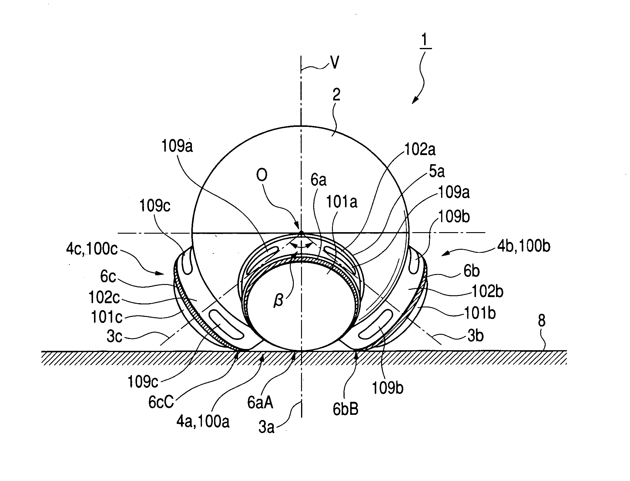
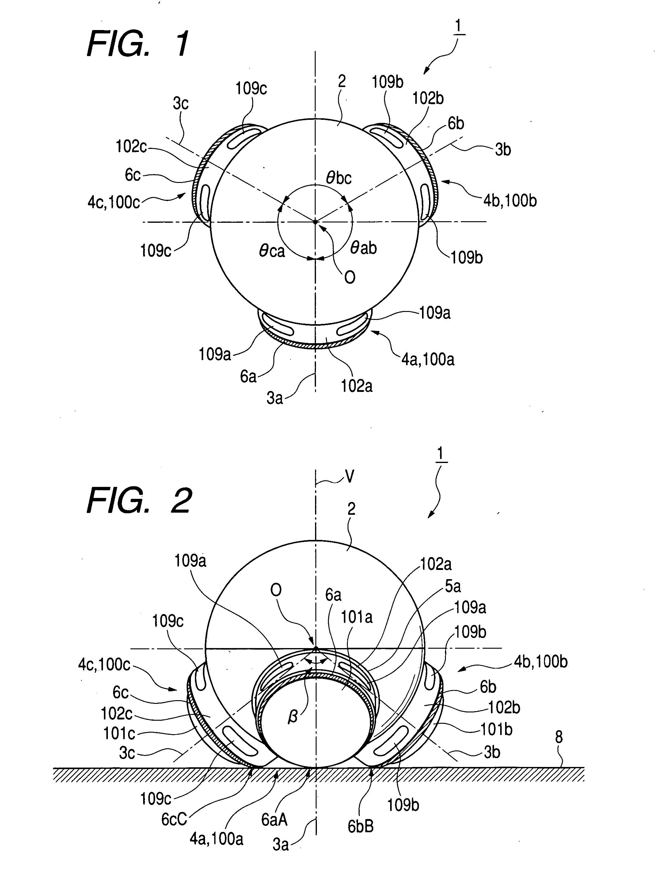
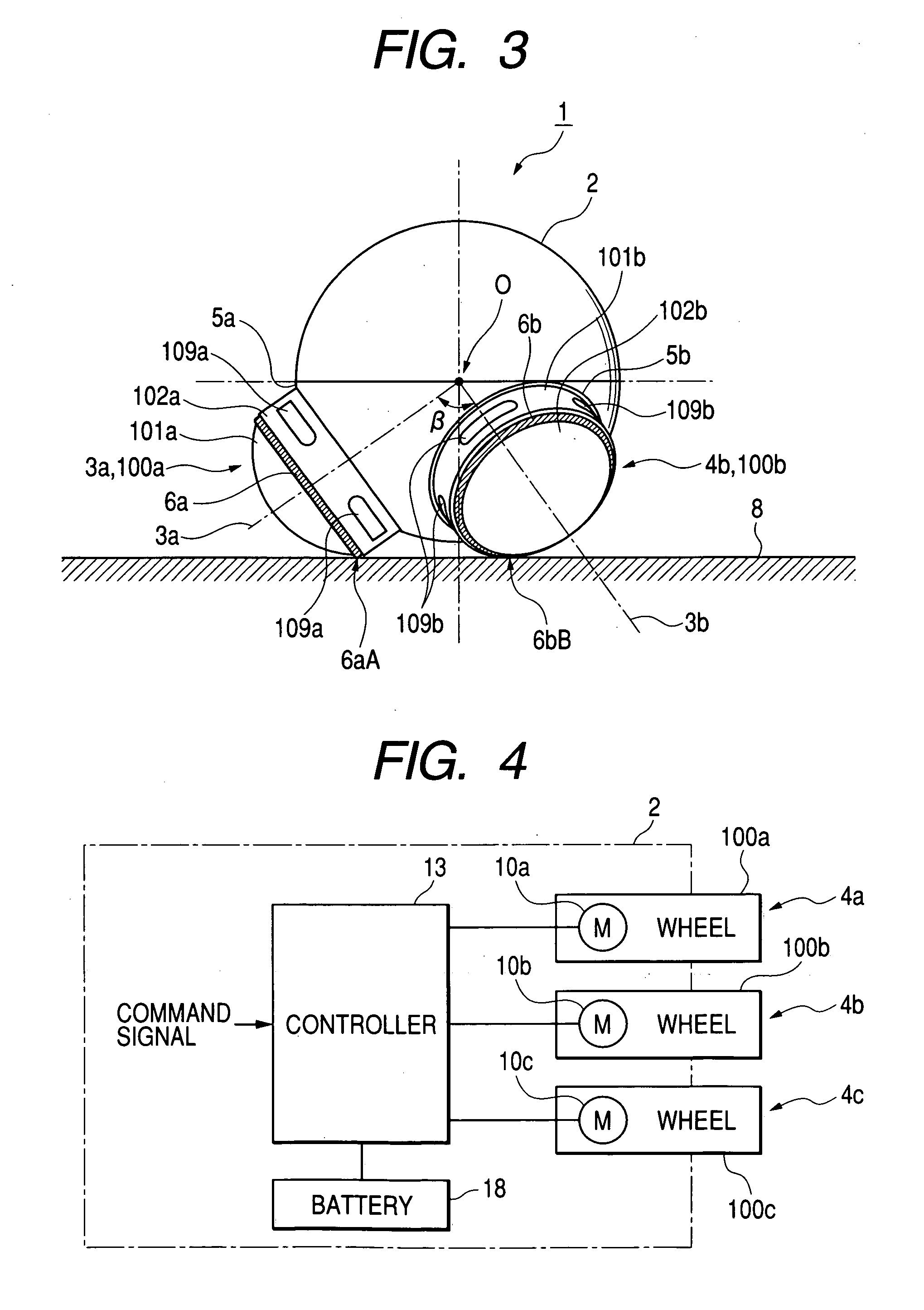
[0285] A fifth embodiment of this invention is similar to one of the first to fourth embodiments thereof except for the following design change. In the fifth embodiment of this invention, rotation axes 3a, 3b, and 3c intersect at a point which is separate from the center O of the approximately spherical casing of the main body unit 2 or 20, and which is on a vertical line V passing through the center O and being perpendicular to the floor surface 8 (see FIGS. 2 and 18). Preferably, the angles between the rotation axes 3a, 3b, and 3c are substantially equal.

sixth embodiment

[0286] A sixth embodiment of this invention is similar to one of the first to fifth embodiments thereof except for the following design change. In the sixth embodiment of this invention, a robot has four or more wheel units extending coaxially with rotation axes respectively.


PUM

PropertyMeasurementUnit
Forceaaaaaaaaaa
Contentaaaaaaaaaa

Abstract

A movable robot includes a main body unit, and at least three wheel units connected with the main body unit. The wheel units have respective contact portions for contact with a floor surface. The contact portions are rotatable about respective axes. The main body unit moves along the floor surface as the contact portions rotate. Lines projected onto the floor surface and originating from the axes of rotation of the contact portions are spaced at substantially equal angular intervals. At most two of the axes are on a common plane. Each of the wheel units includes a motor base, a rotation drive motor supported on the motor base, a casing being rotatable relative to the motor base about related one of the axes and having related one of the contact portions, and a device for transmitting a rotational force generated by the rotation drive motor to the casing.

Description

[0001] 1. Field of the Invention[0002] This invention generally relates to a movable robot of, for example, a self-moving type. This invention specifically relates to a wheeled robot having at least three rotation axes or axles.[0003] 2. Description of the Related Art[0004] Japanese patent application publication number P2001-322079A discloses a humanoid robot or a bipedalism robot having a body equipped with various sensors. The robot body is divided into portions connected by joints which can be driven by actuators. The sensors include gyro sensors and acceleration sensors mounted on the robot body, and encoders located near the joint actuators. The gyro sensors, the acceleration sensors, and the encoders compose a body-posture sensing arrangement. An action / posture management section in the robot operates the joint actuators in response to the output signals of the gyro sensors, the acceleration sensors, and the encoders to properly control the posture of the robot body.[0005] Ja...

Claims


Application Information

Patent Timeline
IPC IPC(8): A63H29/22A63H11/00A63H31/08B25J5/00B25J13/08B60B19/00G05D1/02G06N3/00
CPCB25J5/007B60B19/00B60B2310/305B60B2360/10B60B2360/104B60B2360/3412G06N3/008B60B2360/50B60Y2200/40G05D1/0227G05D1/0246G05D1/0272B60B2360/348
Inventor WAKUI, YOSHIAKI
Owner JVC KENWOOD CORP A CORP OF JAPAN
Why Eureka
Try Eureka